
CNC MACHINING

CNC External Thread Turning: Controlling Pitch, Root and Run-out

Practical DFM for external threads: pre-turn diameter, insert profile, infeed, relief, burrs and inspection to the applicable thread standard.

01

When external thread turning fits

External thread turning synchronizes tool feed with spindle rotation on shafts, connectors and threaded rings. It is flexible for multiple diameters, shoulders and small-to-medium quantities, but success depends on stock diameter, insert geometry, rigidity, infeed, chip control and run-out—not the CNC cycle alone. This article covers external threads and has a different intent from our article on tapping, form tapping and internal thread milling.
02

Define the thread before selecting a tool

The drawing should state thread system, nominal size, pitch or TPI, tolerance class, usable length, hand and governing standard. ISO 965-1:2026 supplies the tolerance system for ISO M threads. Chamfer, shoulder, relief and the condition before or after coating must also be clear. A note such as M20 alone is insufficient.

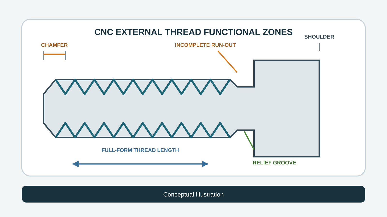
Technical diagram of CNC external thread turning showing entry chamfer, full thread length and run-out relief
Conceptual illustration: key zones to define for external thread turning; not a VietTech production photograph.
FeatureRisk when undefinedWhat to specify
Thread system and pitchWrong profile or programM/UN, pitch or TPI, standard
Tolerance classNo acceptance limitsClass per design standard
Usable lengthToo few full turnsRequired full-form length
Run-outCrash, incomplete thread or burrRelief or allowed run-out
Finish stateTight thread after coatingLimits before or after finish
03

Pre-turn diameter and insert profile

Sandvik Coromant notes that an oversized pre-turned diameter on an external thread creates an excessive first cut and may break the insert. The target must follow the standard, tolerance class and tooling guidance. Full-profile inserts form the crest and root for a defined pitch; partial-profile inserts cover a pitch range but demand closer control of stock diameter and crest deburring.

04

Infeed, chips and rigidity

Radial, modified-flank and alternating infeed distribute cutting load differently. The choice and degressive pass schedule should control chips and edge load for the material, pitch and thread length. Tool overhang, work support, coolant direction and machine acceleration matter. Cutting data must come from the tooling supplier and be validated on the actual setup.

05

Relief and incomplete thread near a shoulder

The tool needs distance to decelerate and withdraw. A full thread against a square shoulder without relief may be incompatible with insert, holder and machine dynamics. A standard relief can help, but it changes section and stress concentration; designers must approve it. Distinguish full-form length, incomplete run-out and assembly clearance.

06

Inspection is more than major diameter

Major diameter alone cannot confirm functional fit. Depending on the requirement, use GO/NO-GO ring gauges, thread micrometers or three-wire measurement, plus pitch/profile inspection where needed. ISO 1502:1996 covers gauges and gauging for ISO metric threads; ISO reports it was confirmed in 2021 and is currently under systematic review. Gauges must match size/class and remain under calibration control.

07

RFQ checklist and limits

Send matching 2D/STEP revisions, full thread callout, hand, usable length, relief, chamfer, material/hardness, finishing state, datum/run-out relationship, inspection method and quantity. This article is based on ISO 965-1:2026, ISO 1502:1996 and Sandvik Coromant application guidance; it does not prescribe universal cutting data.

  • Thread callout, pitch/TPI, class and hand
  • Full-form length, run-out, relief and chamfer
  • Material, hardness and final finish state
  • Datums and related run-out requirements
  • Gauge/report needs, quantity and revision

RELATED PAGES

Circular Runout vs Total Runout: What Is the Difference on a Drawing? ↗How to Request a Quote ↗

FAQ

Frequently asked questions

How does thread turning differ from thread milling?

Turning rotates the work and synchronizes tool feed; thread milling uses a rotating cutter on a helical path.

Why is a thread relief needed near a shoulder?

It provides tool withdrawal space and supports full-form length, but the design must approve its geometry.

Is major-diameter measurement enough?

No. Functional fit also depends on pitch diameter, pitch and profile; suitable gauges or measurement are required.

What is the benefit of a full-profile insert?

It forms root and crest for a defined pitch when the pre-turn diameter is prepared correctly.

What should an RFQ include?

Include the full callout, length, shoulder/relief, material, finish, inspection, quantity and matching drawing/model revision.

CNC MACHINING

Need an external threaded part reviewed?

Send the 2D/3D data, thread standard and class, material, run-out space, finish and quantity for VietTech to review turning, tooling and inspection.REQUEST A QUOTE ↗