
TOLERANCE & INSPECTION

Circular Runout vs Total Runout: What Is the Difference on a Drawing?

Learn the difference between circular and total runout, how datum setup affects results, and how to inspect precision rotating components.

TOLERANCE & INSPECTIONVIETTECH · TECHNICAL RESOURCES
01

Overview

Runout is an important geometric requirement for shafts, bushings, flanges, bearing journals and other rotating components. Excessive runout can contribute to vibration, uneven loading, wear, noise or assembly problems. Circular runout and total runout are easily confused because both are evaluated while the part rotates about a datum axis. Their control scope and inspection procedures, however, are different.

02

What is circular runout?

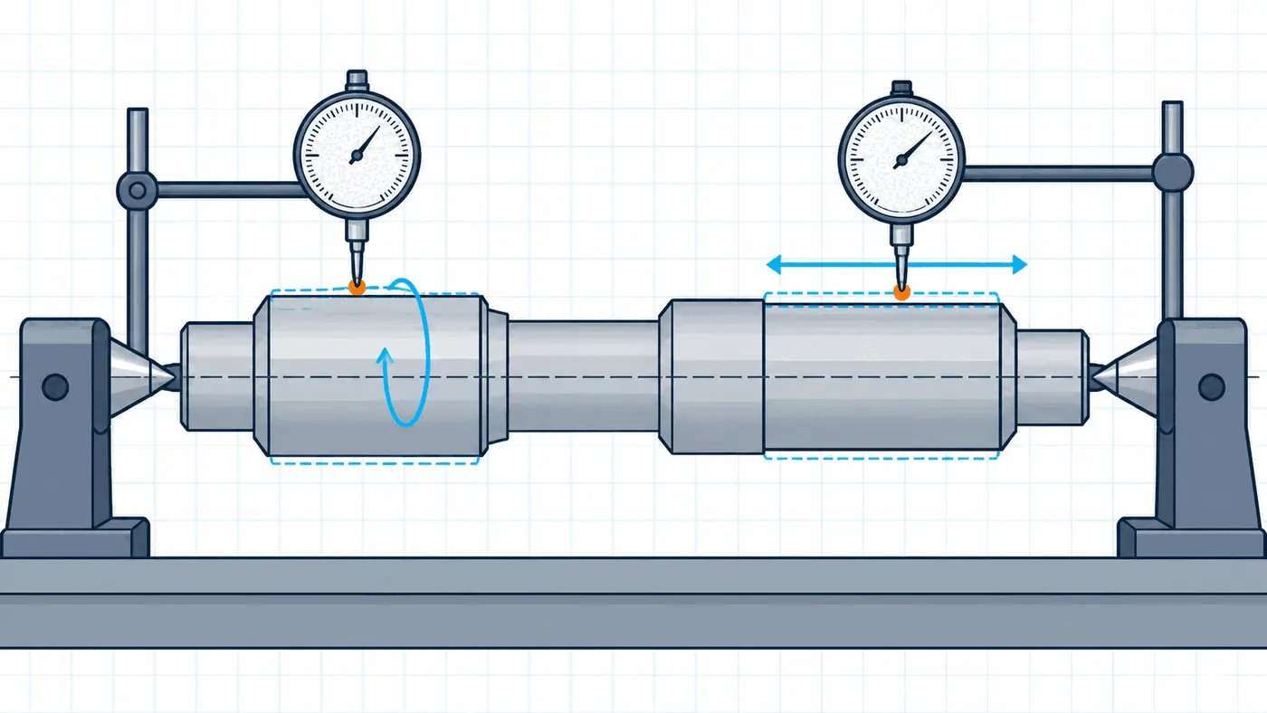
Circular runout controls surface variation at each individual cross-section perpendicular to the datum axis. During inspection, the indicator remains at one axial position while the part completes a full revolution. The difference between the maximum and minimum readings must stay within the specified tolerance. For a cylindrical surface, the reading reflects combined effects at that section, including local circular form, the section's relationship to the datum axis and setup error. Circular runout is therefore not the same as circularity. Circularity is a form tolerance without a datum; circular runout is always evaluated relative to a datum axis.

Circular Runout vs Total Runout: What Is the Difference on a Drawing?
Technical diagram: Circular Runout vs Total Runout: What Is the Difference on a Drawing?. This is not a production photograph; specifications and acceptance follow the drawing.

Where is circular runout useful?

It is useful when function requires control at specific locations, such as a short sealing journal, groove or local rotating diameter. If the full surface length must run consistently, checking only a few sections may not be enough.

03

What is total runout?

Total runout evaluates the entire indicated surface while the part rotates about the datum axis and the indicator traverses along the surface. On a cylindrical feature, it covers variation around the circumference and along the length. It is therefore sensitive to combined effects such as circular form, surface-line straightness, taper, bow and coaxial relationship to the datum. Total runout is often appropriate for long bearing journals, sealing surfaces, ground shafts and diameters that must run consistently over their entire working length. It controls a wider surface scope, but it should not be selected automatically when the function only requires local control.

FactorCircular runoutTotal runout
ScopeIndividual cross-sectionsEntire specified surface
Indicator motionFixed axially during rotationTraverses the surface during rotation
DatumDatum axis requiredDatum axis required
Typical effects includedLocal form and eccentric relationshipAlso lengthwise straightness, taper and bow
Typical useGrooves and short journalsLong journals, sealing and bearing surfaces
04

Why does datum setup determine the result?

The datum axis must be established from the datum feature identified on the drawing before inspection begins. A datum may be derived from one diameter, two common journals, a bore or a datum system. If the inspector uses a convenient chucking surface instead of the specified datum, the result may not represent assembly function. An oval, tapered or damaged datum journal can affect the simulated axis. A chuck, V-blocks and bench centers do not automatically establish the same axis. For tight tolerances, spindle, center, fixture and indicator errors must be sufficiently small compared with the requirement.

Single and common datums

When one datum is referenced, its axis is established according to the governing standard. When two journals establish a common datum, the fixture or mathematical method must represent their joint relationship. One journal should not be used while the other is ignored. The RFQ should identify the governing ISO/JIS or ASME standard because detailed interpretation can differ.

05

Dial-indicator inspection

A practical sequence for a cylindrical surface is: The indicator reading represents the complete measurement system: part, datum, fixture, rotation axis and instrument. If removing and remounting the part changes the result significantly, the cause should be investigated before acceptance.

  • Clean datum surfaces, measured surfaces, centers and fixtures.
  • Mount the part from the specified datum without distorting it.
  • Place the indicator approximately normal to the surface and within its working range.
  • Rotate the part slowly through one full revolution and record maximum and minimum values.
  • For circular runout, repeat at specified or representative cross-sections.
  • For total runout, traverse the entire controlled area while the part rotates and record the full variation.
  • Repeat the measurement to verify setup stability and repeatability.
06

Can a CMM measure runout?

A CMM can collect circular sections and generatrix data, construct alignment from datum features and evaluate geometric relationships. It is useful for complex components, internal bores and numerical reporting. However, a static CMM evaluation is not automatically identical to a dynamic indicator test on a rotating part. Point density, section locations, association algorithms and datum construction all influence results. The acceptance method should be agreed before production: indicator with a rotary fixture or bench centers, CMM, a dedicated roundness instrument, or a defined combination. Results from different methods should not be compared directly unless they use compatible feature definitions and datum setup.

07

Common measurement errors

ErrorEffectControl action
Dirt or burrs on datumTilts or shifts the rotation axisClean and inspect before mounting
Excessive clamping forceDistorts thin componentsReduce force and verify repeatability
Indicator at an angleCosine errorPosition the tip close to normal
Only one section measuredMisses taper or bowMeasure multiple sections or use total runout
Rotation too fastUnstable readingsRotate slowly and consistently
Manufacturing datum used instead of design datumFunction not representedFollow the feature control frame
08

Manufacturing implications

Related rotating diameters should be machined in one setup when practical. Heat-treated shafts may require stock allowance and cylindrical grinding from a consistent datum. Long, thin or unbalanced parts need suitable support and controlled clamping force. Runout capability cannot be inferred from diameter tolerance alone. The drawing should clearly identify datum features, controlled surface, roughness and measurement condition. Very small tolerances also require review of measurement uncertainty and probe access.

09

RFQ checklist

VietTech provides CNC turning, CNC milling, precision grinding, wire EDM and dimensional inspection within the agreed scope. Runout manufacturing and inspection plans are reviewed for the part geometry, tolerance, datum and available equipment; no single capability limit applies to every component.

  • Matching 2D drawing and 3D model with revision.
  • Governing standard and complete feature control frame.
  • Datum feature, datum length and controlled surface area.
  • Size tolerance, surface roughness, heat treatment and finish.
  • Inspection condition before or after processing, free state or assembled state.
  • Quantity, inspection frequency and report format.
  • Customer-mandated acceptance method, if any.

RELATED PAGES

Flatness vs parallelism ↗Surface roughness Ra ↗Grinding after heat treatment ↗

FAQ

Frequently asked questions

Is dial-indicator runout the same as concentricity?

No. Runout is a combined variation observed during rotation. It does not independently separate center offset, form error and setup error.

Does circular runout control the full shaft length?

No. It controls individual cross-sections. Total runout or another suitable specification may be needed for the entire surface.

Can a shaft be rolled on a surface plate to inspect runout?

Only as a comparative check in limited cases. The rolling surfaces may not establish the drawing datum correctly.

Why do the lathe and QC room give different readings?

They may use different rotation axes, clamping forces, datum simulation, indicators and temperatures. The method and repeatability must be aligned.

Can VietTech provide a runout inspection report?

Yes, when the scope, datum, method, frequency and report format are agreed in the RFQ and compatible with the inspection equipment.

TOLERANCE & INSPECTION

Have a rotating part with runout requirements?

Send the drawing, material, quantity, datum axis and post-process tolerance for VietTech to review turning, grinding and inspection.REQUEST A QUOTE ↗