
MACHINING

CNC Turning Long, Slender Shafts: Controlling Chatter, Taper, and Runout

Learn how work support, cutting forces, heat, and process sequence affect chatter, taper, straightness, and runout in CNC turning of slender shafts.

MACHININGTECHNICAL CONCEPT IMAGE
01

What makes a shaft slender?

No single ratio applies to every machine, material, and setup. A higher unsupported length relative to diameter generally reduces bending stiffness, but actual difficulty also depends on chuck projection, the smallest journal, stock allowance, material, workholding, and cutting force. A physically long shaft supported by a tailstock may be more stable than a shorter part projecting far from the chuck. Process planning should therefore evaluate the unsupported span for each operation rather than relying only on overall drawing length.

  • Chatter — Low workpiece or tool rigidity — Wavy marks, noise, inconsistent finish
  • Taper — Radial cutting force deflects the shaft — Different diameters along the length
  • Bending — Residual stress, heat, or unbalanced clamping — Higher runout after unclamping
  • Journal misalignment — Datum changes or unsuitable refixturing — Noncoaxial diameters
  • Chuck-end distortion — Excessive jaw pressure — Jaw marks, out-of-roundness, size error
02

How cutting force deflects the shaft

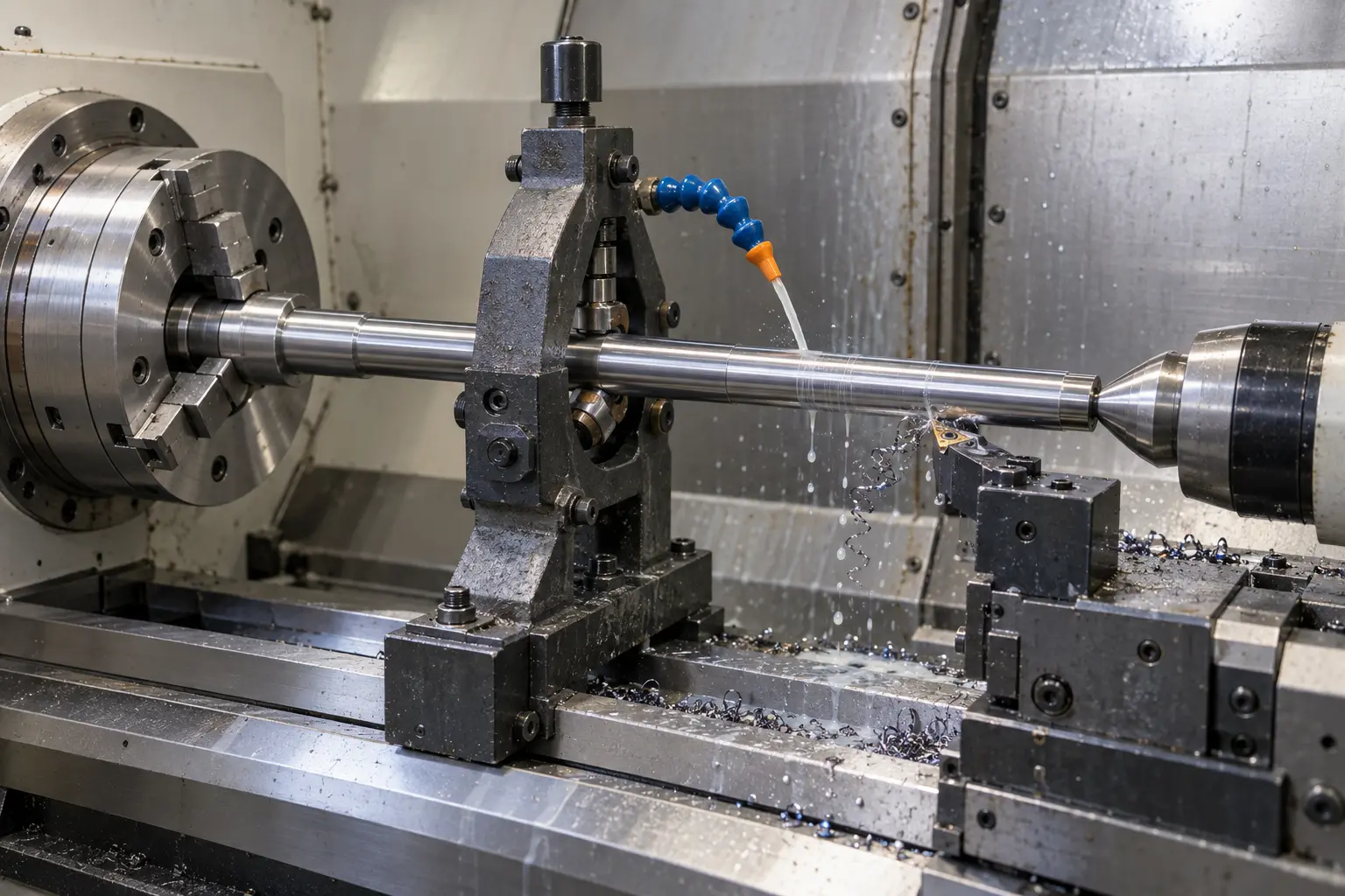
During external turning, the radial component of cutting force tends to push the workpiece away from the insert. Deflection varies with tool position; the center of an unsupported span often moves more than regions near the chuck or tailstock center. The tool removes less material where the shaft escapes the cut, creating form and diameter error. If the tool–workpiece system oscillates, the surface left by one revolution can excite the next revolution and produce regenerative chatter. The resulting helical or wave pattern may be accompanied by insert chipping and unstable dimensions.

Realistic technical concept image for CNC Turning Long, Slender Shafts: Controlling Chatter, Taper, and Runout
Conceptual image created to illustrate the article's technical setup; not an actual VietTech production photograph. Specifications and acceptance follow the drawing/RFQ.
03

Select suitable work support

When geometry permits, a tailstock reduces the free span. The center hole must have suitable geometry, be clean, and receive appropriate lubrication when required. Too little thrust provides inadequate support; excessive thrust can bend the shaft or generate heat at the center. Very long shafts may require a fixed steady rest or follower rest near the cutting zone. The support surface must be sufficiently round and clean, and the rest must be aligned with the spindle axis. Misalignment or excessive pressure can create taper, support marks, or runout. When coaxial relationships among multiple journals are critical, turning between centers can maintain a common rotational datum. Feasibility depends on part length, torque transmission, end geometry, and drawing requirements.

04

Roughing and finishing sequence

Rough turning generates heat and releases residual stress. Finishing one region to final size before removing stock elsewhere may create unbalanced deformation. A controlled process distributes stock removal, allows thermal stabilization when necessary, and leaves consistent finishing allowance. A representative sequence is: This is not a mandatory sequence for every shaft. Material, geometry, tolerance, and production volume determine the final process.

  • Prepare end faces and center holes if tailstock support will be used.
  • Rough all journals while avoiding large differences in remaining stock.
  • Check bend or runout after roughing.
  • Allow thermal stabilization; apply stress relief only when required by the material and specification.
  • Semi-finish and re-establish the datum.
  • Finish coaxial functional surfaces in one setup when practical.
  • Use cylindrical grinding after heat treatment when the specified accuracy or surface condition cannot be controlled reliably by turning alone.
05

Tool geometry and cutting data

A sharp cutting edge with suitable geometry helps reduce radial force. An excessively large nose radius can increase radial load on a slender component, while a very small radius may reduce edge strength or affect surface finish. Feed, depth of cut, and cutting speed should begin with the tool manufacturer’s guidance and then be validated on the actual machine–tool–workpiece system. If chatter occurs, review workpiece projection, tool overhang, center height, chuck runout, tailstock force, steady-rest position, and insert condition. Reducing feed without addressing mechanical instability may create rubbing and make the process less reliable.

06

Control heat and clamping force

A long shaft expands as temperature rises. Measurement taken immediately while the part is warm may differ after it reaches the inspection temperature. Coolant delivery should remain stable and reach the cutting zone; abrupt thermal changes should be avoided. Chuck jaws must transmit sufficient torque without distorting the clamped end. Soft jaws, collets, or suitable protection may be considered for finished surfaces. Jaw pressure and clamping length should be established for the specific part rather than copied across all diameters.

07

Inspect taper, runout, and straightness

Measure diameter at multiple sections to identify taper or barrel-shaped error. Runout must be evaluated relative to the functional datum defined on the drawing, not simply the easiest surface to hold. Shaft straightness and runout are not interchangeable characteristics; a shaft can meet diameter size while remaining bent or misaligned to its rotational datum. At VietTech, inspection may use micrometers, indicators, height gages, or a CMM depending on the size, geometry, and agreed requirement. Support conditions during inspection must be defined for precision shafts because the part’s own weight can influence deflection.

08

Information to include in an RFQ

  • Matching-revision 2D drawings and 3D models.
  • Material grade, condition, and heat-treatment requirement.
  • Overall length, minimum diameter, and permissible support zones.
  • Rotational datum and diameter, runout, cylindricity, or straightness tolerances.
  • Surface roughness and grinding requirements.
  • Areas where chuck or steady-rest marks are prohibited.
  • Quantity, recurring volume, and delivery schedule.
  • Required inspection method or report.

RELATED PAGES

Circular runout vs. total runout ↗Precision grinding after heat treatment ↗VietTech capabilities ↗

FAQ

Frequently asked questions

Does every long shaft require a steady rest?

No. Support depends on the length-to-diameter relationship, unsupported projection, material, cutting force, and geometry. A tailstock may be sufficient in some cases.

Why does a part pass on the machine but fail after unclamping?

Clamping force, tailstock thrust, heat, and residual stress may change the part’s free-state geometry after release.

Is runout the same as shaft bend?

No. Runout is a composite result during rotation and may include bend, journal misalignment, form error, and setup effects.

Can turning meet every runout requirement?

No. Capability depends on size, material, geometry, heat treatment, datum, and inspection method. Some parts require cylindrical grinding.

Is a 3D model sufficient for quotation?

A 3D model supports geometry review, but the 2D drawing is required for tolerances, datums, surface roughness, and inspection requirements.

MACHINING

Have a long, slender shaft to review?

VietTech provides drawing-based machining of shafts, pins, and rotational components. Send the 2D drawing, 3D model, material, quantity, tolerances, and inspection requirements. We will review workholding, support, turning–grinding sequence, and measurement approach before quoting. ---REQUEST A QUOTE ↗