
TOLERANCE & INSPECTION

Hole-Pattern Position Tolerance: Datums, Basic Dimensions, and MMC

Learn how to interpret hole-pattern position tolerance, datum reference frames, basic dimensions, MMC, bonus tolerance, and inspection methods.

TOLERANCE & INSPECTIONVIETTECH · TECHNICAL RESOURCES
01

What does position control?

For a cylindrical hole, position commonly controls the actual hole axis within a cylindrical tolerance zone located at the theoretically exact position. Basic dimensions establish nominal coordinates; the feature control frame establishes allowable variation and the relationship to datums. Position does not replace the hole-size tolerance. Size controls the feature size, while position controls the axis or derived median feature. A hole can meet size but fail position. A well-located hole cannot automatically compensate for an out-of-limit diameter unless the applicable material-condition rules and requirements specifically permit a functional evaluation.

02

Role of basic dimensions

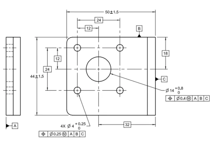
A basic dimension is a theoretically exact value used to establish nominal geometry or location. It does not carry a direct ± tolerance like an ordinary size; allowable variation is defined by the related geometric control. Four holes located by basic coordinates create a theoretical pattern. Position tolerance permits each actual axis to vary within its specified zone relative to the pattern and datum reference frame. A basic dimension should not be converted casually into a ± coordinate tolerance without an approved method and governing standard.

Hole-Pattern Position Tolerance: Datums, Basic Dimensions, and MMC
Technical diagram: Hole-Pattern Position Tolerance: Datums, Basic Dimensions, and MMC. This is not a production photograph; specifications and acceptance follow the drawing.
03

Datum reference frame

A feature control frame may reference primary datum A, secondary datum B, and tertiary datum C. This order is intentional; it defines the sequence used to constrain the part’s degrees of freedom. In CMM inspection, datum-reference-frame construction should simulate the drawing requirement under the governing standard. Selecting a mathematically convenient “best” plane instead of the specified datum can change the result and fail to represent assembly.

  • Primary datum A — Establishes seating plane or primary orientation — Is the surface stable and functional?
  • Secondary datum B — Establishes the next orientation/location — Is it a surface, hole, or axis?
  • Tertiary datum C — Constrains the remaining degree of freedom — Is it accessible during inspection?
  • Basic dimensions — Establish theoretical locations — Are coordinates based on the correct datums?
  • Feature control frame — Defines allowable zone — Are diameter and modifiers present?
04

RFS versus MMC

When no material-condition modifier is shown, position is interpreted under the default rule of the applicable system, commonly referred to as regardless of feature size (RFS) in ASME usage. When MMC is specified, the stated position tolerance applies at the feature’s maximum material condition. For a hole, MMC is the smallest permitted diameter because this leaves the most material. As the actual hole departs from MMC toward a larger size, the difference may become bonus tolerance. Calculation and acceptance must follow the standard stated on the drawing; MMC must not be added when the symbol is absent. Illustrative example: a hole is limited to Ø10.00–10.20 with position Ø0.10 at MMC. At an actual diameter of Ø10.12, departure from MMC is 0.12, potentially increasing the available position zone to Ø0.22 if all drawing and standard rules are satisfied. This example explains the principle and does not replace full drawing review.

05

Why MMC supports assembly function

MMC can establish a functional relationship between feature size and location. A larger bolt-clearance hole provides more assembly clearance and can therefore permit more location variation. This virtual boundary can be evaluated by a CMM or a correctly designed functional gage. MMC is not appropriate for every feature. Precision locating holes, fluid passages, sealing areas, or thin-wall distribution may require location control independent of size. The designer should select a modifier based on function, not merely to increase manufacturing tolerance.

06

Individual-hole location versus pattern relationship

A hole pattern may have two distinct needs: locating the complete pattern relative to datums and controlling hole-to-hole relationship within the pattern. Depending on the governing system and callout, multi-segment controls or pattern specifications may separate these levels. Reading only the final numeric value can miss an important requirement: the pattern may be allowed to shift within one zone while hole-to-hole spacing remains tighter. ISO 5458 provides supplementary rules for pattern and combined geometrical specifications; ASME drawings use their own rules for composite position. Interpretations from the two systems should not be mixed.

07

Inspection methods

A CMM can construct the datum frame, sample multiple points on each bore, and calculate axis position. The inspection program must define datum construction, point count, measurement depth, and evaluation algorithm. Short bores, burrs, and rough surfaces can make the calculated axis sensitive to sampling strategy. A functional gage can rapidly evaluate assembly conditions, particularly for MMC patterns. It must be correctly designed, manufactured, and calibrated. A passing functional gage does not provide the same numerical deviation data as a CMM. Height gages, pin gages, indicators, and surface plates may be appropriate for simpler requirements, but only when the specified datum frame and tolerance zone can be reproduced. At VietTech, inspection is selected according to the drawing, geometry, and agreed reporting requirement. A single tolerance value is not a universal capability for every hole size, depth, and datum system.

08

Common drawing and RFQ issues

  • Applying separate ± coordinates and position without defining priority.
  • Missing datums or datums that cannot be reproduced in manufacturing and inspection.
  • No stated GD&T/GPS standard and revision.
  • Specifying MMC without suitable size control.
  • Failing to define measurement depth or functional bore length.
  • Mismatched 2D and 3D revisions.
  • Requesting a position report without a clear datum frame.
09

RFQ information

  • Governing ISO/JIS or ASME standard and revision.
  • Matching-revision 2D drawing and 3D model.
  • Hole-size limits and basic dimensions.
  • Complete feature control frame, modifiers, and datum order.
  • Actual datum surfaces, contact zones, and cosmetic restrictions.
  • Quantity and CMM-report or functional-gage requirement.
  • Important mating-part and assembly conditions when required.

RELATED PAGES

Circular runout vs. total runout ↗Flatness vs. parallelism ↗Quality and inspection ↗

FAQ

Frequently asked questions

Is position Ø0.10 equivalent to ±0.05 in X and Y?

No. A circular or cylindrical tolerance zone differs from the square zone produced by independent ± coordinates.

Does a correct hole diameter guarantee correct position?

No. Size and position are separate requirements.

Does MMC always provide bonus tolerance?

Only when MMC is specified and the actual feature satisfies the rules of the governing standard.

Do a CMM and functional gage provide the same result?

They serve different purposes. A CMM provides numerical data; a functional gage evaluates an assembly boundary. Their rules must be coordinated.

Is a 3D model sufficient without a 2D drawing?

Usually not. The model may omit datums, modifiers, standards, and reporting requirements unless controlled PMI is provided.

TOLERANCE & INSPECTION

Need a hole-pattern tolerance review?

Send the drawing with its complete feature control frames, governing standard, 3D model, and reporting requirements. VietTech will review machining feasibility, datum establishment, and inspection strategy before quoting. ---REQUEST A QUOTE ↗