
TECHNICAL GUIDE

Climb vs. Conventional Milling: Selecting Feed Direction for Dimensional Stability and Surface Finish

Compare climb and conventional milling by chip formation, cutting-force direction, surface finish, backlash, and workholding to select a stable CNC process.

TECHNICAL GUIDETECHNICAL CONCEPT IMAGE
01

Overview

In CNC milling, changing feed direction can change the result even when the cutter, material, and cutting parameters remain the same. The two fundamental approaches are climb milling and conventional milling. Their effects extend beyond toolpath direction: they influence chip formation, cutting-force direction, vibration, burr location, surface finish, and dimensional stability. Climb milling is generally preferred on rigid CNC machines with controlled backlash. Conventional milling remains valuable when a workpiece has a hard surface scale, stock allowance varies significantly, or the setup makes cutter pull-in undesirable. Process engineers should therefore evaluate the complete machine–tool–fixture–workpiece system instead of applying one rule to every part.

02

What Is the Difference?

Climb milling

At the cutting zone, the cutting edge moves in the same direction as the relative feed. Each tooth enters at a comparatively high chip thickness, which decreases toward nearly zero at exit. This thick-to-thin chip formation lets the edge engage the material decisively and reduces rubbing before effective cutting begins. Under stable conditions, it can support a consistent finish and reduce work hardening caused by rubbing. Cutting force tends to press the workpiece toward its support. However, the tangential force can also pull the cutter or table along the feed direction, so backlash must be controlled and the fixture must resist the pulling load.

Conventional milling

At the cutting zone, the cutting edge moves against the relative feed direction. Chip thickness starts near zero and increases to its maximum at exit. The edge may rub before forming a stable chip, particularly when feed per tooth is too low, the cutter is worn, or the surface has work hardened. Increased friction and temperature can affect tool life and finish. Radial force may tend to lift the workpiece, which requires appropriate clamping. The method is less likely to let the cutter pull itself unexpectedly into the work when feed-system backlash is present.

03

Technical Comparison

This table provides process guidance, not a surface-finish or tolerance guarantee. Actual results also depend on workpiece material, cutter diameter, flute count, tool overhang, axial and radial engagement, feed per tooth, coolant strategy, and machine condition.

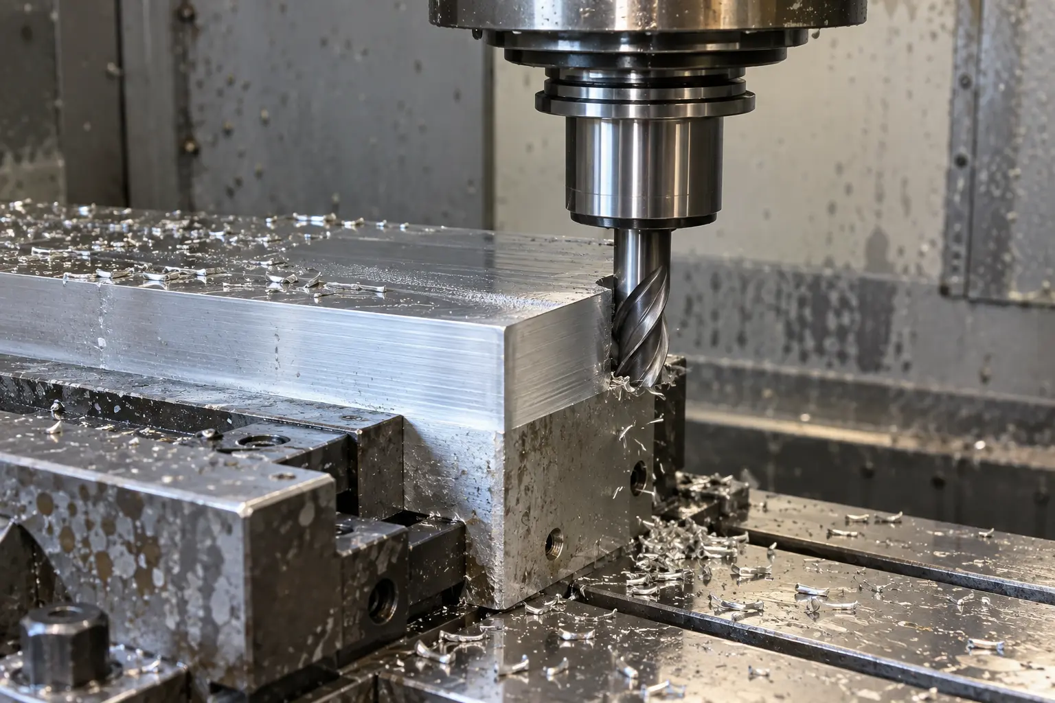
Realistic technical concept image for Climb vs. Conventional Milling: Selecting Feed Direction for Dimensional Stability and Surface Finish
Conceptual image created to illustrate the article's technical setup; not an actual VietTech production photograph. Specifications and acceptance follow the drawing/RFQ.
CriterionClimb millingConventional milling
Cutter rotation relative to feedSame direction at the cutting zoneOpposite direction at the cutting zone
Chip thicknessMaximum to minimumMinimum to maximum
Initial engagementMore decisive chip formationPossible rubbing before stable cutting
Typical force tendencyPresses the workpiece down and pulls with feedPushes the cutter away and may lift the workpiece
Machine requirementGood rigidity and controlled backlashLess sensitive to self-feeding caused by backlash
Surface finishOften advantageous for a stable finishing passMay show more rubbing or visible tool marks
Common considerationsFinishing, rigid setups, modern CNC machinesHard scale, variable stock, machine or setup limitations
04

Effects on Dimensional Accuracy

Feed-system backlash

In climb milling, cutting force can pull the table or cutter in the feed direction. If a leadscrew, nut, or feed mechanism has significant backlash, actual feed may increase unexpectedly. The cutter can take a deeper bite than programmed, causing chatter or dimensional error. Modern CNC machines commonly use preloaded ball screws and closed-loop position control, but machine condition must still be verified in practice.

Tool deflection and workpiece rigidity

A small-diameter end mill, excessive tool overhang, or a slender tool assembly can deflect under load. Thin-wall parts may also deflect during cutting and spring back after unclamping. Changing from conventional to climb milling can reverse the direction of dimensional deviation. A finishing strategy should therefore maintain uniform stock, continuous tool motion, and stable workholding.

Runout and uneven edge loading

Excessive runout causes one cutting edge to carry more load than the others. Vibration and localized wear may then outweigh any theoretical advantage of the milling direction. Before changing the toolpath, verify the holder, tool projection, cutting-edge condition, and cleanliness of the mounting interfaces.

05

When Should Climb Milling Be Preferred?

Climb milling is commonly suitable when: Climb milling does not automatically deliver an acceptable finish. Excessive tool overhang, unsuitable feed, chip recutting, or weak workholding can still cause chatter and dimensional error.

  • The CNC machine is rigid and backlash is low.
  • The workpiece is securely located with clean, adequate support surfaces.
  • The cutter is sharp, runout is controlled, and chip evacuation is effective.
  • A profile finishing pass or stable surface condition is required.
  • The material tends to work harden when rubbed, as can occur with some stainless steels.
06

When Should Conventional Milling Be Considered?

Conventional milling may be appropriate when: When removing an irregular outer layer, conventional milling may allow the edge to enter through cleaner material before reaching the hard surface zone. The process must still prevent excessive rubbing at the initially small chip thickness.

  • A casting or forging has hard scale, oxidation, or substantially variable stock.
  • The machine or feed mechanism does not control backlash adequately.
  • The process must avoid sudden cutter pull-in at a heavy-stock region.
  • Its force direction better supports a specific workholding arrangement.
  • Cutting trials show better burr control or stability along a particular edge.
07

A Toolpath Is Not Always Purely Climb or Conventional

During face milling, pocketing, or closed-profile machining, the cutter center may pass through the workpiece in a way that creates climb milling on one part of the engagement arc and conventional milling on another. When the cutter axis lies within the cut width, both mechanisms may occur during one pass. CAM review should therefore include engagement angle, radial width of cut, entry and exit motion, and chip evacuation. A feed arrow along one edge does not fully describe the cutting condition.

08

How VietTech Selects Milling Direction

For each component, VietTech reviews the drawing, material, stock condition, datum scheme, workholding concept, and inspection requirements before defining the toolpath. The process evaluation typically includes: Climb milling is frequently used for CNC finishing passes. However, selected regions may use a different direction to manage cutter load, burr formation, or thin-wall stability. The final method is based on cutting trials and measurement results, not on the process name alone.

  • Identify datum surfaces and a force direction that will not destabilize the setup.
  • Select the cutter, tool overhang, and feed based on system rigidity.
  • Separate roughing, semi-finishing, and finishing while maintaining suitable finish stock.
  • Inspect the first article and apply tool compensation based on actual measurements.
  • Monitor tool wear and perform in-process dimensional checks as required for the production lot.
09

Information to Include in an RFQ

To support an effective process review, an RFQ should include: VietTech will review manufacturability, workholding, operation sequence, and the inspection plan before responding with a quotation.

  • A 2D drawing with tolerances, datums, and surface-finish requirements.
  • A STEP model when available.
  • Material grade and material condition.
  • Prototype quantity, production quantity, and expected repeat demand.
  • Heat-treatment and surface-treatment requirements, including masking areas.
  • Inspection standards, measurement reports, or traceability requirements.
010

Request an RFQ

Do you have a CNC-milled component with critical dimensions, surface finish, or profile requirements? Send VietTech your 2D drawing, STEP model, material, quantity, and inspection requirements. Our team will review the machining approach and provide an appropriate quotation.

RELATED PAGES

Deep-Pocket Milling: Controlling Chatter, Wall Taper, and Corner Stock ↗CNC Machining Thin-Wall Parts: Reducing Vibration and Distortion ↗

FAQ

Frequently asked questions

Does climb milling always produce a better finish?

No. It often benefits finishing on a rigid system, but cutter condition, runout, parameters, workholding, and chip evacuation remain decisive.

Can a CNC machine use conventional milling?

Yes. Conventional milling is a valid strategy for hard surface scale, variable stock, or a setup that benefits from its cutting-force direction.

Does milling direction affect burr formation?

Yes. Cutting-edge exit direction and edge rigidity affect burr location and size. A separate finishing pass or a change in direction may be used to protect a critical edge.

Why can dimensions change when feed direction is reversed?

The direction of cutting force and tool or workpiece deflection changes. Machine backlash, tool overhang, and clamping force can also influence the result.

Can both methods be used on the same part?

Yes. A program may use different directions for roughing, finishing, scale removal, or burr control at individual features.

TECHNICAL GUIDE

Request a VietTech review

Send the drawing, material, quantity, tolerances and target date for a machining and inspection review.REQUEST A QUOTE ↗