
TOLERANCES & INSPECTION

CMM Datum Setup from a Drawing: Understanding the 3-2-1 Principle

Learn how drawing datums, stable fixturing and part-coordinate alignment affect CMM inspection results.

TOLERANCES & INSPECTIONTECHNICAL CONCEPT IMAGE
01

Why can two CMM reports disagree?

The same part can produce different reported hole-position or perpendicularity values when two programs establish different reference frames. A CMM senses points in its machine coordinate system. The software must construct a part coordinate system from the drawing's datum structure before evaluating the relationships that matter to assembly. Choosing an attractive or accessible surface instead of the functional datum can produce plausible-looking numbers that do not answer the design question. Before programming, identify the controlled feature, specified datums and their order, applicable drawing revision and intended acceptance method.

02

A drawing datum is not just a fixture contact

A datum is an ideal geometric reference established from an actual datum feature using the rules of the drawing. The metal surface marked A is a physical datum feature, not a perfect mathematical plane. Supports and locators simulate a reference during fixturing; they should contact consistently without bending the part. ISO 5459:2024 defines the terminology and interpretation of datum systems, while the practical verification operator may be physical or mathematical. Putting a part bottom-down on a CMM table does not automatically establish datum A if that bottom surface is not the feature identified by the drawing.

Design, machining and inspection references

These may differ because they serve different tasks. A convenient initial alignment can help the probe find the part, but final acceptance must follow the specified datum reference frame.

Best-fit is not an automatic substitute

A global best-fit may help with selected profile comparisons, yet it should not silently replace an A-B-C datum chain specified for position or orientation.

03

What does 3-2-1 actually describe?

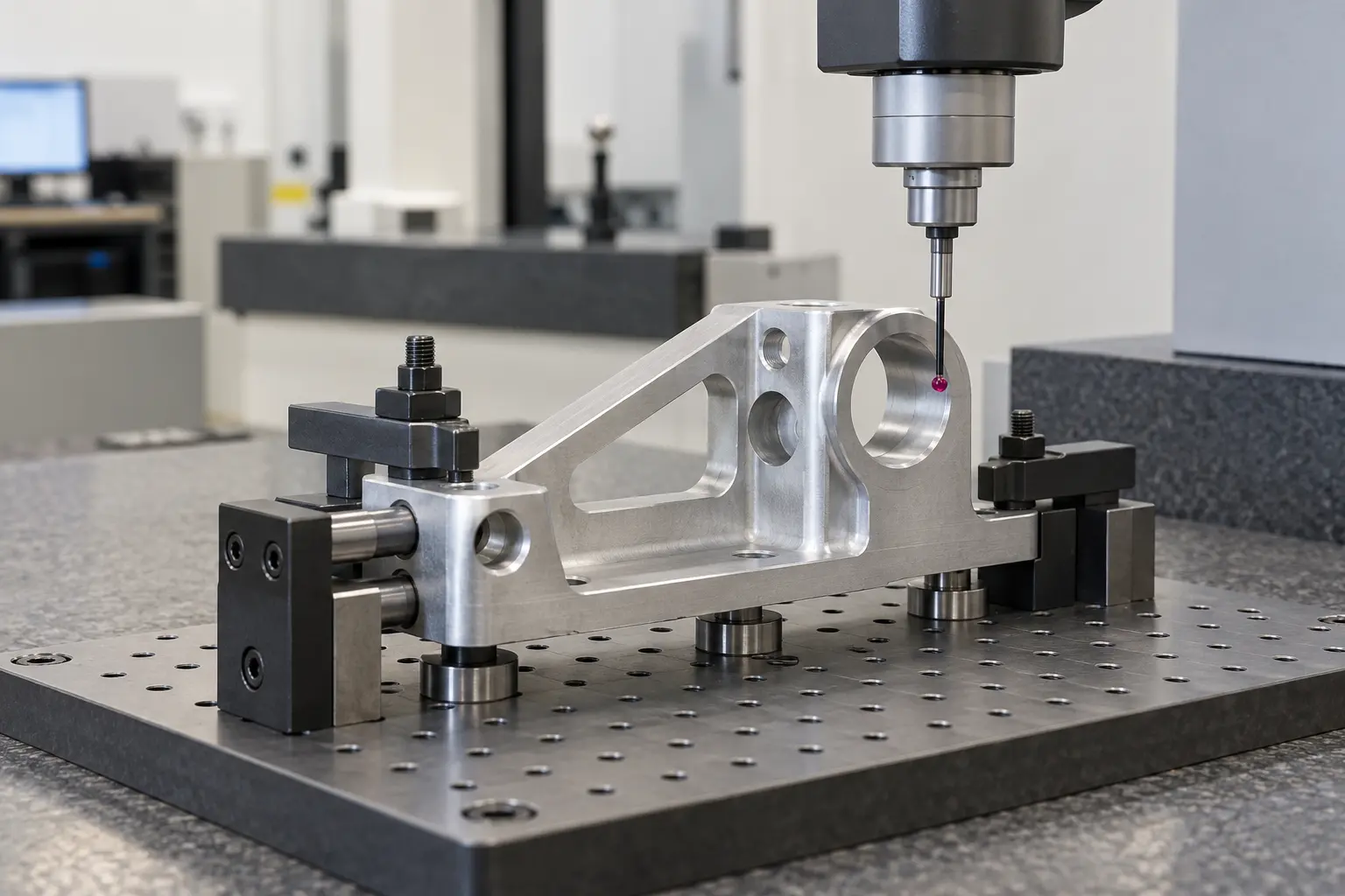
For a suitable block-shaped part with three perpendicular reference faces, the six rigid-body degrees of freedom can be constrained in sequence: three by the primary reference, two by the secondary and one by the tertiary. This is a useful fixture concept and order-of-priority reminder. It does not say that a CMM is allowed to sample only three, two and one points. Too few points can miss form variation, scratches or burrs. Sampling density, where points are taken and how features are fitted must suit the tolerance and geometry. Cylindrical, slotted or special datum systems may not resemble this simple block example.

Mechanical part located by a 3-2-1 fixture beneath a CMM probe
Conceptual image created to show a 3-2-1 datum setup and CMM probe; not an actual VietTech inspection photograph. Datum simulation, clamping, sampling and evaluation must follow the drawing and inspection plan.
Reference rolePurposeCommon mistake
A — primaryEstablish the first functional orientationUsing a convenient face instead of the specified feature
B — secondaryConstrain the remaining orientation in priority orderSwapping B and C
C — tertiaryFinish locating the datum reference frameSetting the origin from an uncalled edge
Inspection strategySample and fit features to suit real geometryToo few points or unremoved burrs
04

A practical CMM alignment workflow

First confirm that the drawing, model and geometric tolerance frames share the correct revision. Clean the datum areas, remove chips and check for burrs. If a finish is specified, establish whether acceptance applies before or after that finish. Seat the workpiece stably and use enough clamping force to hold position without distortion. Inspect and qualify the probe according to the machine procedure. A rough alignment may safely locate the part; then resample the datum features with an appropriate strategy and create the final part coordinate system. Only after that should the program inspect the holes, faces or profiles for acceptance. Rechecking a part after removal and refixturing is a useful way to test setup repeatability.

05

Why can hole-position results shift markedly?

When the origin moves or the axes rotate, a hole far from the reference may report a larger difference even though the hole itself has not changed. Possible causes include choosing the wrong B face, probing a burr, unstable seating, clamping a thin wall out of shape or using a different feature-fitting method. Probe condition, part temperature and room conditions also matter. ZEISS notes that CMM inspection depends on the whole measurement system: machine, sensor, fixture, environment, software and operator workflow. A report stating only 'measured on CMM' does not prove that two evaluations are directly comparable.

06

What should an inspection report retain?

A useful report identifies the applicable drawing revision, inspected feature, datum order, nominal value, limits and result. For demanding work, record the program revision, probe setup, fixture description and measurement conditions under the agreed quality procedure. When a result is close to the limit, review measurement uncertainty and the agreed decision rule before declaring a part conforming or nonconforming. If a datum feature is ambiguous or a callout conflicts with the geometry, request design clarification rather than quietly changing the frame to improve the result.

07

What to include in an inspection RFQ

Provide the revision-controlled 2D drawing and matching 3D model, datum A-B-C requirements, tolerance frames, material, quantity and whether inspection is before or after surface processing. State whether every part or a sample needs inspection, the requested report format and any method-specific rule. VietTech can review CNC machining and suitable measurement, including CMM inspection where appropriate. Feasibility depends on part size, geometry, tolerance and probe access, so a plan should be agreed before manufacture. This helps prevent disputes caused by different datum interpretations applied to the same physical part.

  • Drawing and valid revision
  • Datum sequence and acceptance tolerances
  • Part condition at inspection
  • Sampling and report requirements

RELATED PAGES

Perpendicularity vs. Angularity: How to Read Datum References and Inspect with a CMM ↗Hole-Pattern Position Tolerance: Datums, Basic Dimensions, and MMC ↗

FAQ

Frequently asked questions

Does 3-2-1 mean exactly six CMM touches?

No. It describes how a common fixture model constrains six degrees of freedom. Actual CMM sampling must support the specified geometry and tolerance.

May I select the best-looking face as datum A?

Only if that is the specified or approved datum feature. Easy access alone is not a valid reason.

Why does swapping B and C change the result?

Datum priority governs how the coordinate frame is constrained. A different order may rotate the axes or move the origin.

Can CMM software remove clamping distortion?

No. Mathematical alignment does not reverse physical bending, burr contact or unstable seating.

Which inspection details belong in an RFQ?

Supply datum frames, tolerance callouts, part condition, sampling quantity, report format and the drawing/model revision.

TOLERANCES & INSPECTION

Align the inspection method before machining

Send the drawing with its datums, a 3D model, critical tolerances and report requirements. VietTech will review a suitable manufacturing and inspection approach.REQUEST A QUOTE ↗