
TECHNICAL GUIDE

Perpendicularity vs. Angularity: How to Read Datum References and Inspect with a CMM

Learn how perpendicularity and angularity tolerances differ, how to interpret datum references and tolerance zones, and how to inspect them with a CMM.

TECHNICAL GUIDETECHNICAL CONCEPT IMAGE
01

Overview

On a precision part drawing, a nominal angle such as 90 or 30 degrees does not fully control the orientation of an actual surface or feature axis. An angular size tolerance limits an angle value, while a geometrical orientation tolerance constrains the actual feature within a tolerance zone established from a datum reference frame. Perpendicularity and angularity are two common controls used for this purpose. Correct interpretation supports functional design, stable machining setups, and repeatable inspection. A technically valid CMM report still may not represent assembly function if the datum reference frame is established incorrectly or the measured feature is under-sampled.

02

What is the difference between perpendicularity and angularity?

Perpendicularity controls a 90-degree orientation

Perpendicularity controls the orientation of a surface, centerline, or axis at 90 degrees to the stated datum. Depending on the controlled feature, the tolerance zone may consist of two parallel planes separated by the tolerance value or a cylindrical zone when a diameter symbol is specified for an axis. For example, ⟂ | 0.02 | A applied to a surface requires the entire evaluated surface to remain between two parallel planes 0.02 mm apart and oriented perpendicular to datum A. This does not mean 90 degrees plus or minus 0.02 degree. The value 0.02 defines a linear tolerance-zone width.

Angularity controls a specified orientation other than 0 or 90 degrees

Angularity controls a surface, line, centerline, or axis at a defined basic angle relative to a datum. The nominal angle must be established as a theoretically exact dimension, typically shown as a boxed dimension on the drawing. The value inside the feature control frame defines the width or diameter of the tolerance zone, not an allowable angular error in degrees. For a surface oriented 30 degrees to datum A, a boxed 30-degree dimension and ∠ | 0.05 | A may define two parallel planes 0.05 mm apart, oriented exactly 30 degrees from the datum.

03

Quick comparison

ItemPerpendicularityAngularity
Primary purposeControl a 90-degree orientationControl an orientation other than 0 or 90 degrees
Datum requiredYesYes
Basic angle requiredNo; 90 degrees is inherent in the symbolYes; the angle must be explicitly defined
Tolerance valueZone width or diameterZone width or diameter
Typical controlled featuresSurface, centerline, axisSurface, line, centerline, axis
Typical inspectionCMM, surface plate and indicator, geometry gageCMM, or calibrated angular setup and indicator where suitable
04

How to interpret the feature control frame

Step 1: Identify the controlled feature

Determine where the leader or feature control frame is attached. A frame attached directly to a surface representation generally controls that surface. A frame associated with a diameter size dimension may control the derived axis or centerline of the feature of size. This distinction changes both the tolerance-zone geometry and the inspection strategy. Evaluating a bore axis is not the same operation as evaluating the orientation of its cylindrical surface.

Step 2: Identify the tolerance-zone geometry

The second compartment provides the tolerance-zone size. A diameter symbol indicates a cylindrical zone. Without a diameter symbol, a controlled planar surface is commonly constrained between two parallel planes.

Step 3: Establish the datum reference frame in sequence

Datum references are not interchangeable labels. The primary datum constrains the part first, followed by the secondary and tertiary datums when specified. Machining fixtures and CMM alignments should reproduce the intended degrees of freedom and functional contact sequence.

Step 4: Locate the basic angle for angularity

An angularity callout requires a theoretically exact angle or another unambiguous definition of orientation. If the drawing specifies angularity without fully defining the basic orientation, the supplier should request clarification before quotation or production.

05

Why datum setup changes the result

A physical datum feature contains form error, tool marks, and local variation. The datum itself is a theoretically exact feature established from that physical datum feature in accordance with the governing standard. Therefore, datum A should not be interpreted simply as “place the part on a table and measure it.” On a CMM, the inspector normally probes or scans the datum feature and constructs the alignment. The association method, point density, excluded areas, and workholding condition can affect the result. For a small, interrupted, or functionally supported datum surface, the measurement strategy should reflect how the component is located in assembly.

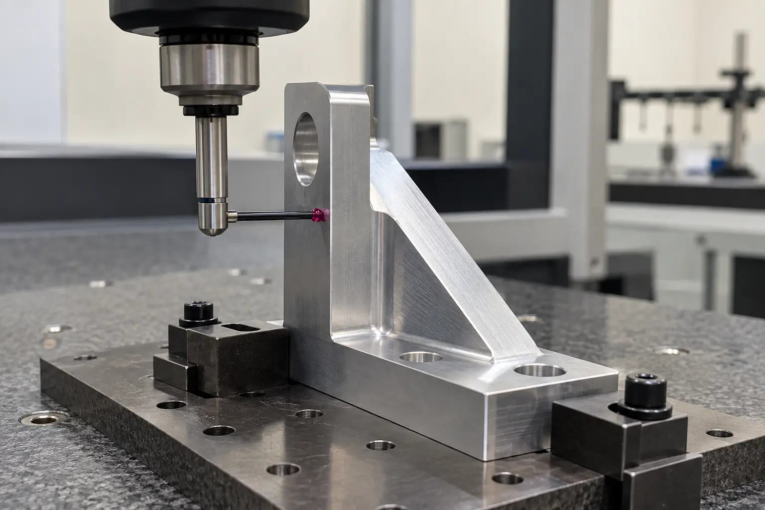
Realistic technical concept image for Perpendicularity vs. Angularity: How to Read Datum References and Inspect with a CMM
Conceptual image created to illustrate the article's technical setup; not an actual VietTech production photograph. Specifications and acceptance follow the drawing/RFQ.
06

Inspection methods

Surface plate and dial indicator

For simple geometry, the primary datum may be seated on a surface plate or fixture while an indicator sweeps the controlled surface. The total indication variation represents change over the inspected travel under that specific setup. This method is efficient for in-process control, but datum flatness, fixture accuracy, sweep length, cleanliness, and clamping force must be managed. For an angled surface, a sine bar, gage blocks, or a calibrated angular fixture may establish the basic angle before the indicator sweep. This comparison method should not automatically be considered equivalent to a CMM evaluation for complex geometry or multi-datum requirements.

Coordinate measuring machine

A CMM is well suited for complex surfaces, bores, shafts, and datum reference frames. A practical sequence is: 1. Clean the part and allow temperature stabilization. 2. Restrain the part securely without introducing measurable distortion. 3. Measure datum features in drawing order and create the alignment. 4. Probe or scan the controlled feature with adequate point density. 5. Evaluate the tolerance zone using the agreed standard and software settings. 6. Report the requirement, measured result, unit, and acceptance status. For a deep bore or a short journal, multiple sections are normally required to represent the derived axis. Measuring only one circle at the bore entrance can miss an axis-orientation error through the full depth.

07

Common engineering and inspection errors

  • Reading a 0.02 mm geometrical tolerance as plus or minus 0.02 degree.
  • Applying angularity without a fully defined basic angle.
  • Selecting a small or unstable datum that does not represent assembly function.
  • Machining the datum and controlled feature in separate setups without a reliable transfer strategy.
  • Distorting a thin component through excessive clamping.
  • Using too few points or measuring only one bore section.
  • Comparing two reports built from different alignment definitions.
08

Process-control recommendations

StageRecommended control
Drawing reviewConfirm the controlled feature, datum references, basic angle, and governing standard
Process planningMachine stable datum features early and minimize setup changes for related features
Rough machiningMaintain appropriate finish stock and monitor stress-related movement
Finish machiningClean locating surfaces and control clamping force and temperature
In-process checkUse an indicator or probing cycle to identify drift before final inspection
Final inspectionUse the agreed datum alignment and consider uncertainty near the specification limit
09

What to include in an RFQ

An effective RFQ should include a legible 2D drawing with GD&T, a 3D model, material, quantity, heat-treatment or surface-finish requirements, the governing drawing standard, and the required inspection documentation. For critical characteristics, specify whether a CMM report is required, the sampling quantity, inspection frequency, and preferred report format. VietTech provides CNC milling, CNC turning, precision grinding, wire EDM, and suitable dimensional inspection, including CMM inspection where required by the feature. The final process and inspection plan is reviewed against part size, workholding, probe accessibility, tolerance, and documentation requirements.

RELATED PAGES

Surface Profile Tolerance: Datums, Tolerance Zones, and CMM Inspection ↗Hole-Pattern Position Tolerance: Datums, Basic Dimensions, and MMC ↗

FAQ

Frequently asked questions

Does perpendicularity 0.02 mean 90 degrees plus or minus 0.02 degree?

No. The 0.02 value normally defines a linear tolerance-zone size in the drawing unit. The zone geometry depends on the controlled feature and whether a diameter symbol is present.

Does angularity require a datum?

Yes. Angularity is an orientation control and must establish its relationship to one or more datums. The theoretically exact angle must also be defined.

Can a machinist square verify a tight perpendicularity tolerance?

A square can support a quick visual or comparative check, but it generally cannot quantify a tight tolerance. A dial-indicator setup or CMM provides more useful quantitative evidence.

Why can CMM and dial-indicator results differ?

Common causes include different datum establishment, evaluated area, point density, sweep length, workholding, and mathematical association. Both methods must evaluate the same defined characteristic before results are compared.

What should be done when a result is close to the limit?

Review repeatability, thermal condition, workholding, evaluation settings, and measurement uncertainty. A disposition should not rely on a single unverified reading.

TECHNICAL GUIDE

Request a VietTech review

Send VietTech your 2D drawing, 3D model, material, quantity, and inspection requirements. Our engineering team will review the datum structure, tolerance zones, workholding approach, and measurement feasibility before providing quotation feedback and an estimated lead time. ---REQUEST A QUOTE ↗