
CNC MACHINING

Internal Corner Radius in CNC Milling: How to Choose R for Cost and Machinability

A DFM guide to selecting internal radii around cutter size, pocket depth, mating parts, inspection, and alternatives for square-corner functions.

01

Why a rotating cutter cannot make a perfectly sharp internal corner

An end mill sweeps a circular path, so two milled walls meet with a finite internal radius. The useful DFM question is therefore which radius preserves assembly function while allowing a sufficiently stiff cutter. Leaving the CAD corner mathematically sharp does not remove the radius; it merely transfers the decision to manufacturing. Specifying a practical minimum radius can reduce tool changes, corner cleanup, cycle time, and quotation uncertainty.
02

The design radius limits cutter size and corner engagement

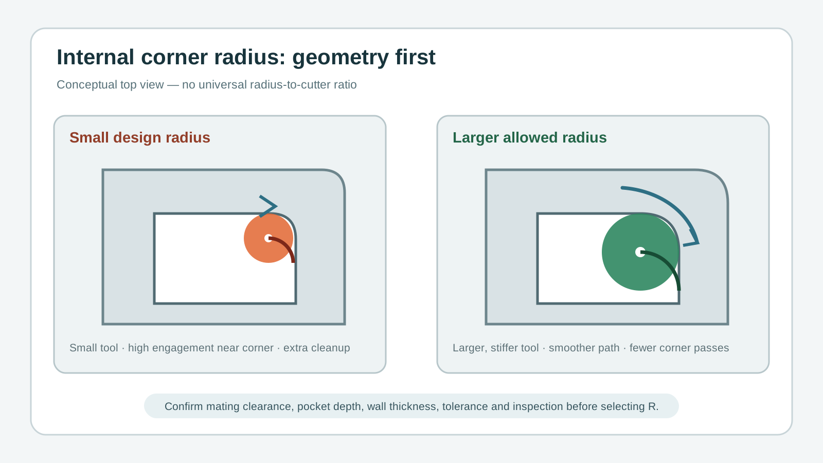
A radius that is barely equal to the cutter radius can produce high engagement as the tool enters the corner, causing a load spike, deflection, or chatter. A larger allowed radius may permit a larger, shorter, stiffer tool and smoother engagement. There is no universal radius-to-cutter ratio: material, depth, overhang, holder, machine, stock, and finish all matter.

Technical comparison of small and larger internal radii in a CNC-milled pocket
Conceptual illustration: a larger corner radius often permits a stiffer cutter and smoother toolpath. This is not an actual VietTech production photograph; dimensions and tooling require drawing-specific review.
Design choiceTypical machining effectConfirm
Larger functional clearance radiusLarger tool and fewer cleanup passes may be possibleMating-part clearance and function
Small radiusSmaller tool, rest machining, longer reach and more timeDepth, overhang and inspection access
Square-corner functionRelief, EDM, or mating-part change may be neededMaterial, wire access, blind geometry and approval
03

Pocket depth amplifies a small-radius requirement

A small radius near the top of a shallow pocket may be routine, while the same radius at the bottom of a deep pocket can require a long-neck tool or a small holder. Greater overhang reduces stiffness and raises deflection risk. Designers should separate vertical corner radius from the wall-to-floor radius when their functions differ, and avoid applying one small radius to an entire pocket unnecessarily.

04

Options when an assembly needs a nearly square corner

Possible design solutions include a dog-bone or T-bone relief, a chamfer or radius on the mating part, staged milling, or EDM where geometry and material permit. Wire EDM requires conductive material and wire access and cannot create a closed blind pocket. Every relief or process change modifies geometry, stiffness, sealing, stress, or cost, so it needs design approval.

05

Plan roughing, rest machining, and finishing as a sequence

A robust process removes most stock with a larger tool, distributes finish allowance, then uses a smaller tool only where necessary. Rest-machining data must reflect the previous cutter and remaining stock; otherwise the cleanup tool may meet an unexpected load in the corner. Constant-engagement or adaptive paths reduce load variation but cannot remove the geometric limit of cutter radius.

06

Tolerance, finish, and inspection

If the radius is only tool relief, avoid unnecessarily tight tolerance. A functional radius should identify its controlled area, tolerance, finish, and datum relationship. Profile instruments, optical systems, a suitably configured CMM, or functional gages may be used depending on size and access. Passing radius alone does not prove the adjacent walls or floor satisfy position or orientation.

07

DFM and RFQ checklist

Provide controlled 2D and STEP files, pocket depth, wall thickness, minimum or acceptable radius range, mating-part geometry, relief permission, tolerance, finish, material, quantity, and post-processing. Identify areas where EDM, start holes, or tool witness marks are not allowed. VietTech reviews milling, workholding, and inspection for each drawing rather than assuming every small radius is practical.

  • 2D and STEP at the same revision
  • Minimum or acceptable R range
  • Pocket depth, floor radius, and wall thickness
  • Mating part and allowed relief
  • Tolerance, finish, datums, and inspection
  • Material, quantity, treatment, and delivery
08

Technical references and limits

This guide is cross-checked against Sandvik Coromant and Seco Tools guidance on pocket milling, engagement, overhang, and stable toolpaths. Manufacturer recommendations must still be matched to the exact cutter, material, machine, and setup. The guide does not replace stress analysis, product standards, or cutting trials; safety-critical geometry changes require design-owner approval.

RELATED PAGES

Deep-Pocket Milling: Controlling Chatter, Wall Taper, and Corner Stock ↗Wire EDM Explained: When Should It Be Used for Precision Parts? ↗How to Request a Quote ↗

FAQ

Frequently asked questions

Can CNC milling make a perfectly square internal corner?

Not with a conventional rotating end mill. A finite radius remains; relief, EDM, or a mating-part change may be needed.

Should the corner radius equal the cutter radius?

Avoid that when function allows, because engagement rises sharply at the corner. A larger radius offers more tooling choices.

Does a larger radius always reduce cost?

No. Assembly, depth, tolerance, quantity, and other features still govern the total process.

Can a dog-bone replace a square corner?

It can create assembly clearance but changes geometry and potentially stiffness, sealing, or stress, so it needs approval.

What does VietTech need for review?

Send matching 2D/3D data, material, pocket depth, allowable radius, tolerance, quantity, and mating-part requirements.

CNC MACHINING

Need an internal radius reviewed before release?

Send the drawing, model, material, pocket depth, minimum R, tolerance, and quantity. VietTech will review tooling, toolpath, workholding, and inspection before quotation.REQUEST A QUOTE ↗