
CNC MACHINING

CNC milling tool runout: What to check when flute wear is uneven

Separate tool runout from part runout, document measurement locations and check the holder and cutting edges before changing milling parameters.

01

Check the assembly before changing feed

When some milling flutes are worn while others remain relatively intact, inspect how the cutter is held. Runout can distribute cutting load unevenly and mislead an investigation into cutting conditions or tool material. Uneven wear is not proof of runout, however: chips, impacts, edge geometry and entry conditions also deserve attention. This guide addresses the spindle–holder–tool assembly rather than runout tolerances on the manufactured part. The aim is to test a plausible cause before changing several parameters at once.
02

Tool runout and part runout are different requirements

Tool-assembly runout describes changes in the position of a surface or cutting edge as the assembly rotates about its working axis. Drawing runout requirements apply to the component and its specified datum. A well-mounted cutter does not establish geometric conformity of the part, and an acceptable part does not prove that tool life is optimized. Keep process-condition checks separate from product acceptance.

Radial versus axial variation

Radial variation influences how teeth share the cut. Axial height differences on a face mill can leave one edge doing much of the finishing. A measurement in one direction does not represent both.

TIR is not always eccentricity

Total indicator reading is the maximum minus minimum indication under the stated measurement conditions. TIR equals twice the eccentricity only for an ideal circular section with pure eccentric displacement. Do not extend that relation automatically to helical edges or surfaces with form error.

03

Document where the reading was taken

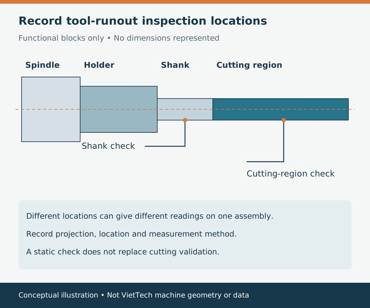
Two people can obtain different readings on the same assembly if they measure at different distances from the holder nose. Record contact position, tool projection, instrument, rotation method and the surface being checked. A reading near the holder does not replace assessment of the actual cutting region. With small tools or interrupted edges, contact force and geometry may distort the result. Select a suitable method and consider non-contact measurement when needed. Mentioning a method here does not claim that VietTech owns the specialist equipment.

Conceptual spindle, holder, tool shank and cutting region with two different inspection locations
Conceptual illustration. Blocks identify inspection locations; this is not a VietTech equipment drawing or measurement record.
04

Inspect each interface, not just the new holder

Start with clean, undamaged mating surfaces. Chips or dents can disturb seating even when individual components have good specifications. Check the shank, collet, nut and holder against the manufacturer’s instructions, including gripping diameter, insertion length and tightening torque. For indexable cutters, check pockets, support faces and screws. Do not grind reference surfaces or over-tighten to force runout away. Suspected spindle problems belong with qualified personnel following the maintenance procedure.

Location or conditionConfirmDo not assume
Spindle–holder interfaceClean, intact, correctly seatedA new holder makes the whole assembly sound
Shank–clamping systemSuitable diameter and grip lengthMore tightening is always better
Cutting regionMethod suits edge geometryShank measurement covers every cutter
Indexable face millPockets, supports, screws and edge heightEvery surface step is a program error
05

Change one factor and keep the evidence

Where the procedure allows, compare a verified reference assembly with the suspect assembly at the same measuring position. Changing one factor at a time avoids confusion from replacing the cutter, holder and cutting parameters together. Record before-and-after readings and repeatability after remounting. Work only in the safe machine state specified by the equipment instructions. Never position an indicator or adjust an assembly during automatic spindle operation. Static results still need comparison with behavior under cutting load.

06

Runout, balance and deflection are not interchangeable

Low runout at inspection speed does not prove that the assembly is balanced for its operating speed. Balance concerns mass distribution; deflection depends on force and stiffness. An assembly may look satisfactory in a static check yet vibrate in service because of projection, loading, workholding or dynamic conditions. Balancing cannot replace a runout check. Nor is there one micrometre limit for every cutter. Read the manufacturer’s specification conditions and establish an appropriate operation-specific criterion.

07

Validate the cut and communicate functional requirements

After correcting a verified cause, reassess dimensions, finish and wear pattern through a controlled trial. A supplier’s tool-life improvement percentage is not a universal promise for every material. In an RFQ, identify functional surfaces, tolerances, roughness and reporting needs. A particular holder usually need not be mandated unless the design or specification requires it. VietTech reviews CNC machining and inspection within confirmed capability; any specialist heat or surface treatment is coordinated with partners and confirmed separately.

08

References and limits

Reviewed on 20 October 2026 against guidance from Harvey Performance, BIG DAISHOWA and Sandvik Coromant, plus HAIMER holder information. These sources support assembly-control principles, not a universal acceptance standard. The original diagram is conceptual and does not depict actual VietTech equipment or operations. Apply machine, cutter and holder limits to the specified combination and conditions.

RELATED PAGES

Radial chip thinning: When should CNC milling feed increase? ↗Deep-Pocket Milling: Controlling Chatter, Wall Taper, and Corner Stock ↗Circular Runout vs Total Runout: What Is the Difference on a Drawing? ↗How to Request a Quote ↗Harvey Performance — Reducing Tool Runout ↗BIG DAISHOWA — Tool holders and tool life ↗Sandvik Coromant — Milling cutter maintenance ↗HAIMER — Tool-holder specifications ↗

FAQ

Frequently asked questions

Does a good reading at the holder prove the tool tip is satisfactory?

No. Location and assembly geometry matter. Assess the cutting region with an appropriate method.

Will additional tightening reduce runout?

Not necessarily. Incorrect torque can damage or deform components. Follow the clamping-system instructions.

Does low runout mean the assembly is balanced?

No. Runout and imbalance are different characteristics that must be managed for the application.

Is one TIR limit suitable for every cutter?

No. The cutter, holder, measurement position, speed and operation requirements all matter.

CNC MACHINING

Send VietTech your CNC machining requirements

Share the drawing, material, quantity and critical surfaces so VietTech can review a suitable machining and inspection approach.REQUEST A QUOTE ↗