
CNC TECHNOLOGY

Radial chip thinning: When should CNC milling feed increase?

Understand radial engagement, chip thickness and feed per tooth, then check CAM compensation to avoid double adjustment and excessive corner loading.

01

A light cut is not automatically an efficient cut

Side milling at a small radial engagement may show low spindle load while tool wear or surface quality remains disappointing. One possible cause is a chip that is too thin for the cutting conditions. Reducing engagement without changing feed per tooth does not preserve maximum chip thickness. This is not permission to raise feed whenever the load display looks low: tool wear, runout, vibration and chip evacuation must also be considered. This article addresses radial chip-thinning compensation, rather than the choice between climb and conventional milling.
02

Separate feed per tooth from chip thickness

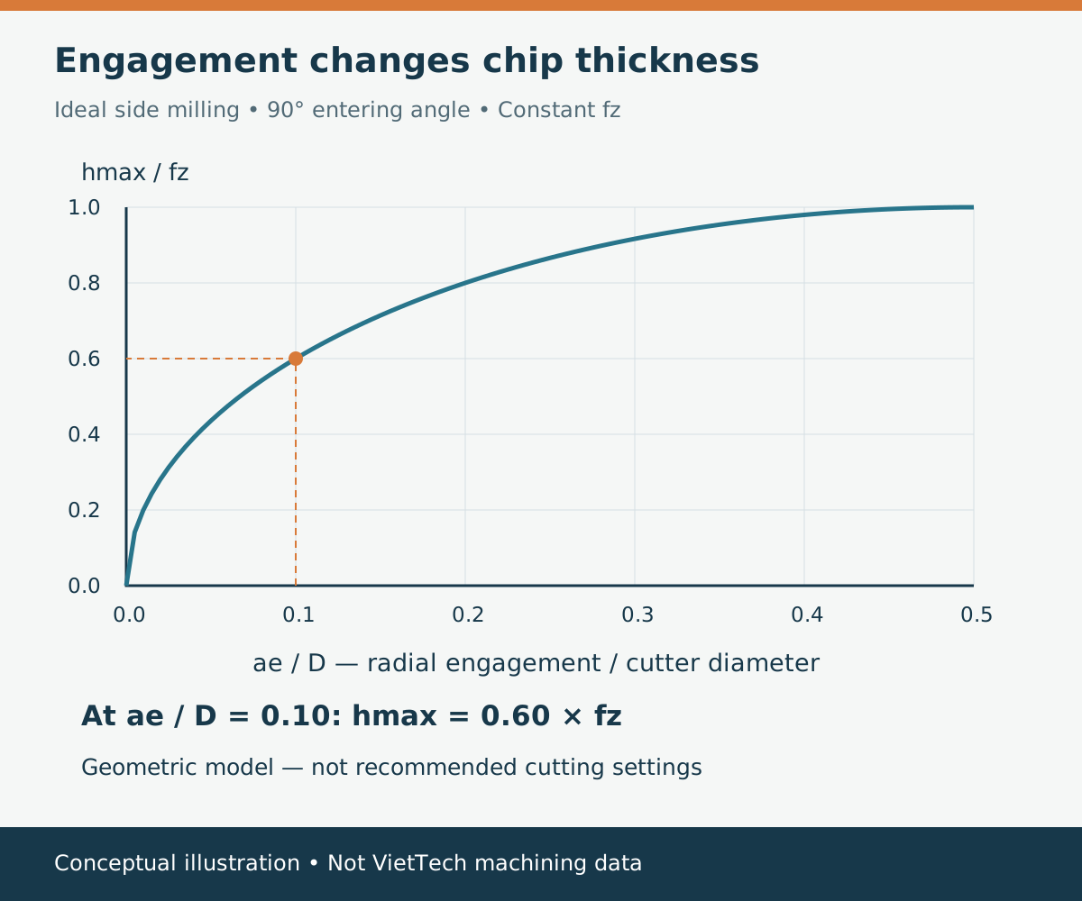
Feed per tooth, fz, is normally expressed in mm/tooth. Radial depth of cut, ae, is the width of engagement, and D is the cutting diameter. Chip thickness changes as the edge moves through the engagement arc. For ideal side milling with a straight cutting edge and a 90-degree entering angle, maximum chip thickness becomes smaller than fz when ae is below half the diameter. Before adjusting anything, determine whether the tool supplier recommends fz or a target chip thickness, and whether the recommendation already accounts for radial engagement.

Graph of maximum chip thickness divided by feed per tooth against radial engagement divided by cutter diameter
Conceptual illustration calculated from ideal 90-degree side-milling geometry. Not cutting-trial data or a VietTech machining recommendation.
03

A mathematical example, not a cutting recipe

For 0 < ae/D ≤ 0.5 in that simplified model, let r = ae/D. Then hmax/fz = 2√(r(1−r)). At r = 0.10, the ratio is 0.60. Holding fz unchanged therefore gives a maximum chip thickness equal to 60% of fz. To retain the same hmax as a half-diameter engagement, the geometric feed multiplier is approximately 1.67. This calculation does not establish a safe machine setting. Confirm material, tool geometry, overhang, axial depth, workholding and machine limits. Ball-nose, round-insert and chamfer tools, as well as curved toolpaths, require their own applicable treatment.

ae/DApproximate hmax/fzfz multiplier for equal hmax
0.100.601.67
0.250.8661.155
0.501.001.00
04

Audit the CAM settings before editing the feed

Find where cutting data is controlled: the tool library, operation parameters, CAM compensation or a manual control override. If the library already supplies corrected fz for the selected engagement, another multiplier would compensate twice. Record the input value, its meaning, the assumed engagement and the point where compensation is applied. Inspect the posted program, not just the CAM input box.

Converting fz to table feed

For a conventional end mill, vf = fz × z × n, where z is the effective tooth count for the cutter configuration and n is spindle speed in rpm. Do not substitute the instantaneous number of teeth touching the workpiece for z. If speed changes, review table feed to retain the intended fz.

Corners and remaining stock matter

A lightly engaged straight pass can enter a corner with much greater contact. Uneven stock, material left by the previous tool and an incorrect entry position can invalidate the original assumption. Compensation for a light straight cut must not be applied indiscriminately to the whole path.

05

Run a controlled trial and record evidence

Start with the tool maker’s data for the actual material and simulate the remaining stock. Confirm workholding, tool clamping length, appropriate cooling and a clear chip-evacuation route. During a controlled trial, observe cutting sound, load, edge condition, surface quality and dimensions after the part has stabilized. Change a controlled group of parameters so that its effect remains interpretable. Vibration, chipped edges or rubbing marks call for investigation, not another automatic increase in feed. Low displayed load alone does not demonstrate a healthy process.

06

Compensation cannot repair a weak process

Runout can distribute load unevenly between teeth. Excessive overhang or a compliant workpiece wall can cause deflection even with a narrow cut. A large axial engagement increases the participating edge length and needs separate assessment. A shorter cycle is useful only if dimensions, finish, tool life and consistency remain acceptable. Functional surfaces still need an appropriate finishing strategy and inspection plan; a successful roughing pass is not acceptance evidence. Chip-thinning compensation is one part of cutting-data selection, not a replacement for sound tooling and workholding.

07

What to put in an RFQ

Customers generally do not need to prescribe fz. Provide material and condition, geometry, functional tolerances, finish, quantity and acceptance criteria. Identify restrictions on tool marks, burrs or surface lay. Separate mandatory process restrictions from suggestions so the supplier can evaluate alternatives. VietTech assesses CNC machining and inspection within its confirmed scope. Cutting parameters are selected for the individual job; a theoretical multiplier is not a promise of a universal productivity gain.

08

References and limits

Reviewed on 18 October 2026 against Sandvik Coromant’s milling definitions and formulas and Harvey Performance’s chip-thinning guidance. The table and graph are original calculations from an idealized model, not production measurements. Different cutter geometry and circular interpolation require the relevant tool-maker and CAM guidance. This is a technical discussion aid, not a ready-to-run machining program; the responsible process engineer must validate actual conditions.

RELATED PAGES

Climb vs. Conventional Milling: Selecting Feed Direction for Dimensional Stability and Surface Finish ↗Deep-Pocket Milling: Controlling Chatter, Wall Taper, and Corner Stock ↗Internal Corner Radius in CNC Milling: How to Choose R for Cost and Machinability ↗How to Request a Quote ↗Sandvik Coromant — Milling formulas and definitions ↗Harvey Performance — How to Combat Chip Thinning ↗

FAQ

Frequently asked questions

Does low ae always require a higher fz?

No. First check whether the supplier or CAM data already includes compensation, then assess stiffness, path changes and machine limits.

Can every tool use a 1.67 multiplier?

No. It is a geometric example at ae/D = 0.10 under the stated assumptions, not a universal setting.

Is chip-thinning compensation the same as increasing rpm?

No. It addresses feed and chip thickness. Spindle speed must also match the appropriate cutting speed.

Does this formula apply to full-width slotting?

Do not apply the stated ae/D ≤ 0.5 expression to full-width slotting. Use data and chip-evacuation guidance for that operation.

CNC TECHNOLOGY

Send a CNC machining RFQ

Send the controlled drawing revision, material, quantities and acceptance requirements so VietTech can assess machining and inspection options.REQUEST A QUOTE ↗