
TECHNICAL GUIDE

Cut Tapping, Form Tapping, and Thread Milling: Which Method Should Be Used for CNC Internal Threads?

Compare cut tapping, form tapping, and CNC thread milling by material, blind-hole conditions, chips, torque, accuracy, inspection, and cost.

TECHNICAL GUIDETECHNICAL CONCEPT IMAGE
01

Overview

Internal threads are common in housings, plates, fixtures, manifolds, bushings, and general machine components. Three widely used CNC methods are cut tapping, form tapping, and thread milling. Each can produce an acceptable thread when correctly applied, but they differ in how the profile is generated, how chips are managed, torque demand, suitable materials, and dimensional adjustment. The nominal diameter alone is not enough to select a process. The thread standard and class, material, blind or through condition, effective thread length, post-machining finish, quantity, and inspection method must be reviewed together.

02

How does a cutting tap produce a thread?

A cutting tap removes material with cutting edges and generates chips. Flute geometry and chip direction must therefore match the hole condition.

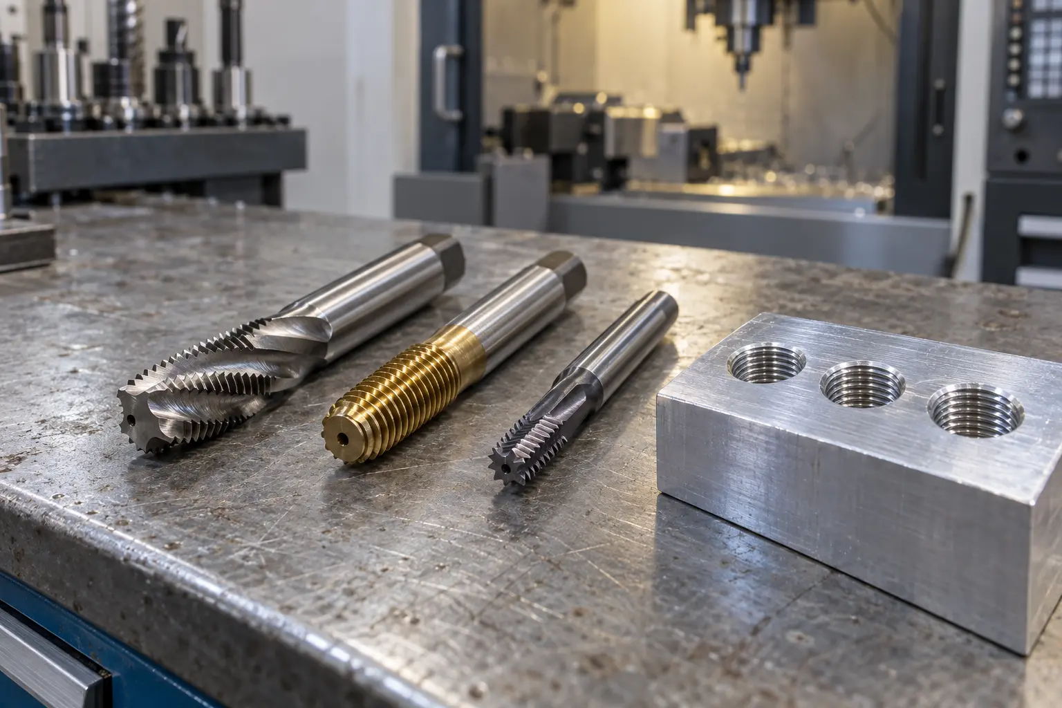
Realistic technical concept image for Cut Tapping, Form Tapping, and Thread Milling: Which Method Should Be Used for CNC Internal Threads?
Conceptual image created to illustrate the article's technical setup; not an actual VietTech production photograph. Specifications and acceptance follow the drawing/RFQ.

Through holes and blind holes

For a through hole, a spiral-point tap can push chips forward and out through the bottom. For a blind hole, a spiral-flute tap commonly carries chips back toward the entrance. These are general directions; the final choice depends on material, depth, coolant delivery, and the toolmaker’s application guidance. Cut tapping is widely available for steel, stainless steel, aluminum, and many engineering materials. It covers a broad range of small and medium thread sizes and can provide short cycle times in repeat production. The main risks are chip packing, edge chipping, and tap breakage. A blind hole needs extra bottom clearance for the tap chamfer and chips, so drilled depth cannot simply equal the effective thread length. Spindle-feed synchronization, tool runout, and coolant condition also affect results.

03

How is form tapping different?

A forming tap displaces ductile material instead of cutting it. Because it does not need large chip flutes, the tool core can be more rigid, and chip entanglement is eliminated. The method is generally suited to materials with sufficient ductility, including appropriate aluminum alloys, low-carbon steels, and selected stainless steels.

Pre-hole diameter is critical

The pre-hole for form tapping is normally larger than the cut-tap drill for the same nominal thread and must be controlled closely. A hole that is too small raises torque and can break the tool or overfill the thread profile. A hole that is too large reduces thread formation and may cause a gauge failure. A cut-tap drill chart must not be reused for a forming tap. Form tapping generally requires higher torque and effective lubrication. It is not the default choice for brittle materials, low-elongation materials, or specifications that prohibit formed threads. Any drawing, industry, or customer restriction on the thread-making process takes precedence.

04

When should CNC thread milling be considered?

Thread milling combines a thread mill with helical interpolation. The cutter orbits the hole axis while moving in Z to generate the pitch. Since the cutter is smaller than the thread diameter, chips have an evacuation path, and a tool failure is less likely to block the entire hole cross-section than a broken solid tap.

Dimensional adjustment

Thread size can be adjusted with cutter-radius compensation within the process limits. Some cutters can machine multiple diameters that share the same pitch and profile, but the approved range of the specific tool must be verified. Thread milling is useful for high-value components, larger threads, difficult materials, or applications where pitch diameter needs controlled program compensation. The method requires a CNC capable of suitable interpolation, stable workholding, and a correct toolpath. Cycle time per hole is often longer than tapping, particularly for many small holes. Tool overhang, runout, and rigidity affect taper and thread form.

05

Comparison of the three methods

This table is a selection guide, not a process guarantee. The final method must reflect the actual material, part geometry, machine, holder, cutting tool, and acceptance criteria.

CriterionCut tappingForm tappingThread milling
MechanismRemoves materialPlastically displaces materialHelically interpolated milling
ChipsProduces chipsChipless formingProduces relatively small chips
Material rangeBroad with the correct tap geometryRequires sufficient ductilityBroad, subject to tool and machine capability
Pre-holeBased on cut-tap requirementsLarger and tightly controlledMust provide cutter and profile clearance
Torque/loadMedium to high, material-dependentCommonly higherCutting load distributed through milling
Size adjustmentLimited, mainly tool-dependentLimited and sensitive to pre-hole sizeCutter-radius compensation is possible
Blind holesRequires chip and bottom-clearance controlNo cutting chips, but lead clearance remains necessaryFlexible depth control
Productivity for many small holesCommonly highCommonly high in suitable applicationsMay be slower
Tool-breakage consequenceBroken tap can be difficult to removeBroken tap can be difficult to removeLess likely to occupy the full bore
06

The pre-hole controls thread quality

Before threading, the hole diameter, roundness, straightness, depth, and position must be controlled. Burrs or a sharp entrance can interfere with assembly. A suitable chamfer supports tool entry, but it must not reduce the specified effective thread length. There is no universal pre-hole diameter for every material and method. It must be selected from the thread standard, tolerance class, specific tool, and toolmaker’s recommendation. If plating or anodizing follows machining, the drawing must state whether the acceptance size applies before or after finishing and whether the thread is masked.

07

Thread inspection requires more than trying a bolt

A mating bolt can reveal an obvious problem, but it does not replace a specified gauge. The GO plug gauge must enter the required thread length under the applicable inspection rules. The NO-GO member must not exceed the permitted engagement. Gauges must match the thread system, pitch, class, and calibration requirements. Special applications may require pitch-diameter measurement, profile verification, or a first-article report. Chip removal, preservation oil, and coating condition should be agreed before final inspection.

08

Information to include in an RFQ

VietTech machines internal threads on CNC-milled and CNC-turned components and inspects them against the agreed drawing requirements. The method is evaluated from material, dimensions, quantity, and access; one tool or process is not assumed for every component.

  • Complete designation, such as M6 × 1–6H or 1/4-20 UNC-2B.
  • Blind or through hole, effective thread length, and drilled depth.
  • Material, hardness, and heat-treatment condition.
  • Number of threaded holes per part and order quantity.
  • Surface finish, masking, and the required acceptance condition.
  • Mandatory thread-making method when controlled by design or specification.
  • GO/NO-GO gauging, inspection report, and traceability requirements.

RELATED PAGES

Drilling, Boring or Reaming: Which Process for Precision Holes? ↗How to Specify Materials and Surface Finishes in an RFQ ↗

FAQ

Frequently asked questions

Does a formed thread always have greater strength than a cut thread?

Formed threads can provide favorable surface properties in suitable ductile materials, but they are not automatically superior in every application. Design requirements, material, thread fill, and the governing standard determine suitability.

Can cut tapping and form tapping use the same drill size?

Normally no. Form tapping requires a larger and more tightly controlled pre-hole. Use data for the exact tap and workpiece material.

Can thread milling be used for small threads?

Yes, if a suitable cutter, machine accuracy, and access are available. For a large number of small holes, tapping may still provide a shorter cycle.

Why can a bolt feel tight even when the GO gauge passes?

Possible causes include burrs, coating, entry-thread damage, contamination, an incorrect mating bolt class, or long engagement. Both components and surface conditions should be checked.

When should plated or anodized threads be inspected?

Follow the drawing. If the functional size applies after finishing, coating allowance, masking, cleaning, and final-state inspection must be planned accordingly.

TECHNICAL GUIDE

Request a VietTech review

Send the 2D drawing, 3D model, full thread designation, material, quantity, and finishing requirements. VietTech will review the pre-hole, chip evacuation, thread depth, machining route, and inspection method before quotation. ---REQUEST A QUOTE ↗