
TECHNICAL GUIDE

Induction Hardening Depth: Specification, Grinding Allowance and Inspection

Learn how to specify induction hardening depth, surface hardness, hardened zones, grinding allowance and inspection for CNC-machined parts.

TECHNICAL GUIDEVIETTECH · TECHNICAL RESOURCES
01

Overview

Induction hardening is commonly applied to shafts, pins, gears, cams, rollers and surfaces exposed to wear or contact loading. A localized area is heated by an electromagnetic field and rapidly quenched, producing a hardened surface zone while retaining suitable core properties. A drawing note that states only “induction harden to 55–60 HRC,” however, does not fully define the requirement. A clear RFQ should identify the material and prior condition, areas to be hardened and excluded, surface hardness, hardened depth, inspection locations, and final dimensional condition. Without these details, the machining supplier and heat-treatment provider may interpret the same nominal hardness requirement differently.

02

How induction hardening changes the surface

Unlike carburizing or nitriding, induction hardening does not intentionally add an element to the surface. Martensitic transformation depends on the substrate's carbon content, alloying elements, prior microstructure and quench response. Changing the steel grade, diameter or incoming heat-treated condition can therefore change the result even if the equipment program remains unchanged. Coil geometry, frequency, power, heating time, scan speed, coil-to-part gap and quench arrangement determine the heating pattern. Shoulders, grooves, holes, tooth roots and abrupt section changes can concentrate or reduce energy and alter cooling. They may create a shallow zone, a soft spot, overheating or cracking risk. The drawing should identify the start, stop and permitted transition regions.

Induction Hardening Depth: Specification, Grinding Allowance and Inspection
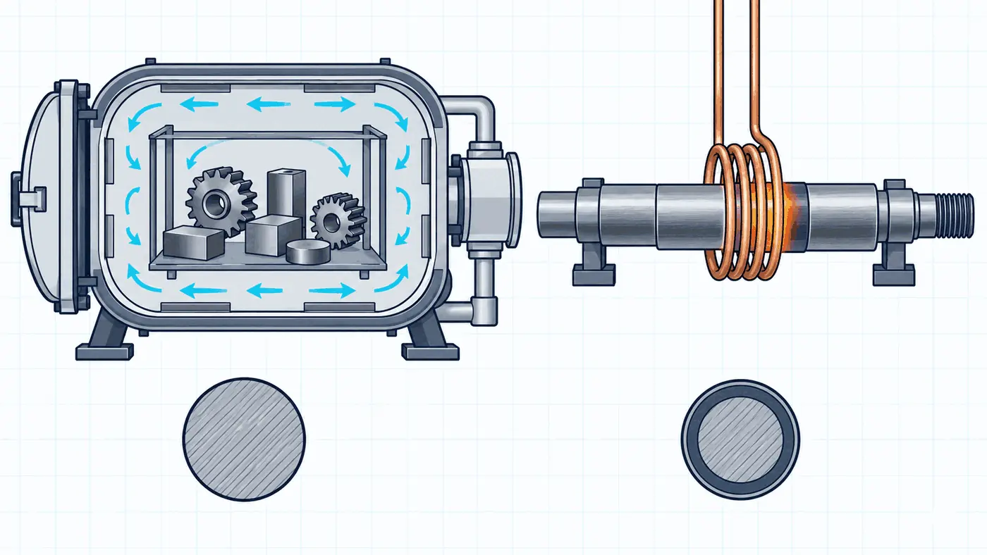
Technical diagram comparing induction heating with a furnace heat-treatment route; confirm case depth using the specified hardness method.
03

Effective and total hardened depth are different

“Case depth” is often used as a general expression, but it does not always refer to the same characteristic. Surface hardening depth (SHD) is measured from the surface to the point where a defined hardness limit is reached under the applicable standard or technical agreement. Total hardening depth extends to the location where the hardening effect can no longer be identified by the selected evaluation method. Because the criteria differ, a drawing should not state only “case depth 1 mm.” It should identify SHD or total depth, the allowable range, hardness limit, test scale and governing standard. ISO 18203:2026 specifies methods for measuring surface-hardened layers, including the surface hardening depth produced by flame or induction hardening.

Item to defineClear RFQ informationRisk if omitted
Material and prior conditionGrade, standard and incoming hardness/propertiesTarget hardness or depth may not be achieved
Hardened zoneBounded area, length and transition allowanceWrong area, overheated corner or soft zone
Surface hardnessRange, scale and test locationResults cannot be compared consistently
Hardened depthSHD or total depth, limits and standardDifferent interpretations of “case depth”
Final conditionBefore or after grinding and subsequent treatmentHardened layer removed or final size missed
Inspection methodSampling, sectioning, report and acceptance ruleInsufficient evidence for acceptance
04

Why surface hardness alone is insufficient

An HRC or HV reading on the surface only describes the response at the test location and within the indentation's influence. It does not establish the subsurface hardness profile or hardened depth. A common SHD verification method is to section the part at a defined location, prepare the metallographic sample and perform a microhardness traverse from the surface toward the core. The section must represent the functional or worst-case zone. One cross-section may not represent a long part or several different diameters. Destructive verification is normally performed on a sample component, representative coupon or agreed sampling quantity. Nondestructive methods such as eddy-current, ultrasonic or magnetic techniques can support process monitoring, but they should be qualified and correlated with the reference method before being used for acceptance.

05

Machining and grinding allowance after hardening

Induction hardening can cause bending, ovality, size change or cracking because of thermal gradients and transformation stresses. Long, thin-walled or deeply grooved components and abrupt section changes require early risk assessment. Where size, roundness, runout or roughness tolerances are tight, the process may include semi-finish machining, induction hardening, inspection and final grinding. Grinding allowance should not be a universal number. Too little stock may not clean up distortion; too much can remove a significant part of the hardened layer or cause grinding burn. If grinding follows heat treatment, the hardness and depth requirements should normally be tied to the final delivered surface. Reliefs, chamfers and non-hardened zones should also be defined to reduce ambiguity and stress concentration.

06

Recommended control sequence

Before heat treatment

- Verify the material certificate and incoming condition. - Inspect dimensions, stock allowance, straightness and surface condition. - Establish the datum system for before-and-after measurements. - Agree on hardness locations and sectioning positions.

After heat treatment

- Inspect appearance, heat pattern and evidence of cracking. - Measure hardness at the specified locations. - Check distortion, runout and critical dimensions. - Verify SHD by sectioning at the approved frequency. - Confirm adequate hardened material remains before finish grinding.

After final machining

- Reinspect dimensions, geometry and surface finish. - Reconfirm hardness or depth if required in the final condition. - Link the heat-treatment certificate, inspection data and lot traceability.

07

RFQ checklist

VietTech provides CNC turning, CNC milling, precision grinding, wire EDM and dimensional inspection within the agreed scope. Induction hardening is coordinated with a specialist partner. VietTech reviews the machining route, allowance and inspection plan against the drawing; it does not apply one universal hardness or depth capability to every material and geometry.

  • Matching revisions of the 2D drawing and 3D model.
  • Steel grade, material standard and incoming condition.
  • Hardened, non-hardened and permitted transition zones.
  • Surface-hardness range, scale, locations and number of tests.
  • SHD or total depth, limits and measurement standard.
  • Final dimensions, geometric tolerances and roughness after grinding.
  • Quantity, test pieces, sampling frequency and certificate requirements.

RELATED PAGES

Vacuum vs Induction Hardening: Which Process Fits a Machined Part? ↗When Is Precision Grinding Required After Heat Treatment? ↗

FAQ

Frequently asked questions

Are high-frequency hardening and induction hardening the same?

In common manufacturing usage, both terms generally refer to electromagnetic induction heating followed by rapid quenching. Frequency is only one of the variables that affects heating distribution and hardened depth.

Can an HRC surface test verify induction hardening depth?

No. Surface hardness and hardened depth are different characteristics. SHD commonly requires a microhardness traverse on a prepared cross-section.

Should hardened depth be specified before or after grinding?

The acceptance condition must be stated. If the surface is ground after hardening, the functional requirement normally needs to be verified on the final delivered surface.

Does induction hardening eliminate distortion?

No. Local heating can limit the affected volume compared with through hardening, but distortion still depends on material, geometry, fixturing, heating pattern and quenching.

Can VietTech provide heat-treatment and inspection reports?

Reports can be coordinated when their type, measured characteristics, sampling frequency and inspection method are agreed during RFQ review and are compatible with the participating facilities.

TECHNICAL GUIDE

Request a VietTech review

Do you need a shaft, pin, gear or localized surface induction hardened? Send the drawing, material, quantity, hardened zone, hardness, depth and inspection requirements. VietTech will review the machining–heat treatment–grinding sequence and propose a suitable route before quotation. ---REQUEST A QUOTE ↗