
TECHNICAL GUIDE

Straightness vs. Flatness: How to Interpret Tolerance Zones and Select an Inspection Method

Learn how straightness and flatness differ, how their tolerance zones work, and when to use a surface plate, indicator, or CMM for inspection.

TECHNICAL GUIDETECHNICAL CONCEPT IMAGE
01

Overview

Straightness and flatness are form controls. They limit the geometry of the specified feature itself and generally do not require a datum. Their essential difference is scope: straightness may control a surface line element or an extracted median line, while flatness controls an entire surface. Confusing these controls can lead to an invalid inspection plan. Several acceptable straight traces do not establish that the full surface is flat. Likewise, sweeping a dial indicator across a part on a surface plate does not automatically reproduce the standardized flatness evaluation unless support, alignment, sampling, and data processing are appropriate.

02

What does straightness control?

Straightness of a surface line element

When straightness is applied to a surface, the inspection typically evaluates a line element in the indicated direction. The actual line must remain between two parallel straight lines separated by the tolerance value. This control is useful for long edges, guide surfaces, or longitudinal sections. The result depends on the location and direction of each trace. When the drawing is not explicit, design and inspection teams should agree on the number, position, and evaluation length of the traces. A single centerline trace may miss edge distortion.

Straightness of an extracted median line

Straightness can also control the extracted median line of a shaft or bore. When a diameter symbol is used for the tolerance zone, the median line must remain inside a cylindrical zone of the stated diameter. This is different from checking one surface line on the outside diameter. For a feature of size, the callout may also involve a material requirement under the governing drawing standard. The feature-control frame and leader placement must therefore be interpreted together.

03

What does flatness control?

Flatness applies to an entire surface. All evaluated points on the actual surface must lie between two parallel planes separated by the tolerance value. The planes are not required to be parallel to a datum because flatness is an independent form control. Flatness does not directly control the orientation of one surface to another. If a face must be both flat and parallel to datum A, a parallelism control may also be required. A thickness tolerance does not automatically replace a flatness requirement.

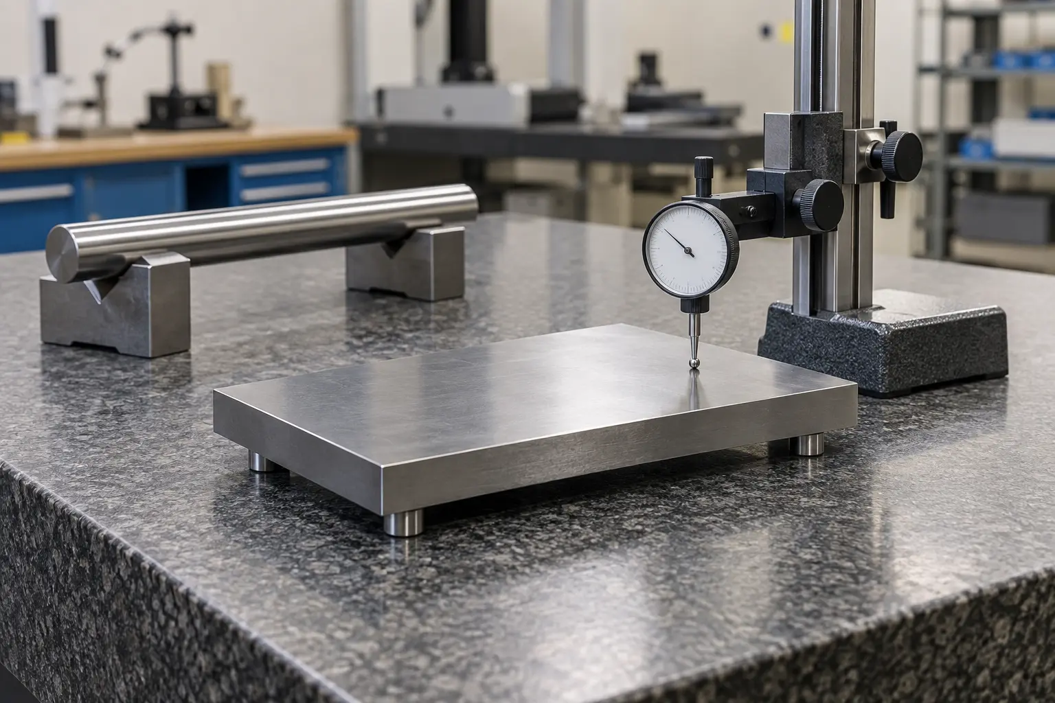
Realistic technical concept image for Straightness vs. Flatness: How to Interpret Tolerance Zones and Select an Inspection Method
Conceptual image created to illustrate the article's technical setup; not an actual VietTech production photograph. Specifications and acceptance follow the drawing/RFQ.
04

Quick comparison

ItemStraightnessFlatness
Controlled featureSurface line element or extracted median lineEntire surface
Typical tolerance zoneTwo parallel lines, or a cylinder when Ø is specifiedTwo parallel planes
Datum requiredGenerally noNo
Common methodsIndicator, contour instrument, CMMSurface plate and indicator, CMM, scanning system
Common riskWrong trace direction or insufficient tracesSparse sampling or clamping the part flat
Do not confuse withParallelism or cylindricityParallelism or surface roughness
05

Flatness is not parallelism or roughness

Flatness describes the form of one surface. Parallelism controls its orientation relative to a datum. A face can be very flat yet tilted relative to another face. It may also appear generally parallel while containing unacceptable waviness. Surface roughness describes short-wavelength irregularities and is commonly specified with Ra or another texture parameter. Flatness addresses larger-scale form. A ground surface with low Ra can still fail flatness because of heat, residual stress, or fixturing.

06

Selecting an inspection method

Surface plate and dial indicator

This is a practical shop-floor method for evaluating a planar surface. The part is supported at defined locations, and the indicator follows a planned grid. Results are affected by surface-plate quality, support points, measuring force, temperature, and the method used to establish the reference plane. Placing the measured face directly on the plate and indicating the opposite face may combine thickness variation with the relationship between the two faces. The setup must isolate the feature specified on the drawing.

Straightedge and feeler gauge

A certified straightedge and feeler gauge may be suitable for screening, assembly checks, or relatively broad requirements. The method observes only the directions in which the straightedge is placed and is operator-dependent. It should not be the sole method for a tight, traceable requirement unless the customer has accepted it.

Coordinate measuring machine

A CMM can collect discrete points or scan the surface, construct the feature, and calculate deviation in inspection software. It supports repeatable programs and documented reports, including areas that are difficult to access with an indicator. Results still depend on sampling density, point distribution, stylus configuration, filtering, and the association algorithm. A sparse pattern can miss a localized high or low area. Large, ground, or visibly wavy surfaces may require denser sampling in high-risk regions and a measurement uncertainty suitable for the tolerance.

07

Fixturing, temperature, and free-state requirements

A thin component may be forced flat on the machine or inspection fixture and spring back after release. When the drawing requires free-state evaluation, the setup must not use clamping force to correct the part during measurement. Heat from machining, handling, or the environment can also alter size and form. Before tight-tolerance inspection, clean the component, remove burrs at support points, and allow thermal stabilization. Large parts require support that limits gravitational deflection without overconstraining the component.

08

Manufacturing considerations

Face milling may create form error through cutter condition, spindle alignment, clamping, and heat. Surface grinding can improve flatness and roughness but may still create distortion through grinding heat, wheel condition, or residual stress. The final process must be selected according to material, overall size, wall thickness, and the specified tolerance. A stable route typically establishes reliable locating surfaces, balances stock removal, leaves appropriate finishing allowance, controls temperature, and verifies the part after stabilization. Flatness capability cannot be confirmed from the tolerance value alone without reviewing the total surface size and part geometry.

09

RFQ checklist

VietTech provides CNC milling, CNC turning, precision grinding, and inspection to drawing requirements. The inspection method is selected according to feature type, tolerance, size, accessibility, and measurement uncertainty rather than assigning one instrument to every flatness requirement.

  • Matching 2D drawing and 3D model revisions.
  • Governing tolerancing standard, units, and drawing defaults.
  • Controlled surface or line element and evaluation length or area.
  • Straightness, flatness, parallelism, thickness, and roughness requirements.
  • Inspection condition: free state, functional fixture, or defined support method.
  • Material, heat treatment, finish, and process stage at which the tolerance applies.
  • Quantity, first-article requirement, sampling density, and report format.

RELATED PAGES

Flatness vs. Parallelism on a Machining Drawing ↗CNC Turning Long, Slender Shafts: Controlling Chatter, Taper, and Runout ↗

FAQ

Frequently asked questions

Does flatness require a datum?

No. Flatness is a form control applied to the surface itself. Use an appropriate orientation control when the surface must be related to another feature.

Does straightness apply only to an edge?

No. It can control a surface line element or the extracted median line of a feature of size, depending on the callout.

Are four corner points enough to verify flatness?

Usually not. Four points can miss a high, low, or wavy region between them. Sampling density must reflect the surface size and tolerance.

Is total indicator variation equal to flatness?

Not automatically. The reading depends on support, reference setup, and scan path. The evaluation procedure must reflect the defined tolerance zone.

Does a low Ra value guarantee a flat surface?

No. Roughness and flatness control different scales of surface deviation. A smooth surface can still be bowed or warped.

TECHNICAL GUIDE

Request a VietTech review

Send VietTech your drawing, 3D model, material, quantity, and inspection-report requirements. Our engineering team will review the tolerance zone, part support, manufacturing strategy, and suitable inspection method before providing a quotation. ---REQUEST A QUOTE ↗