
CNC MACHINING

CNC Lathe Soft Jaws: Controlling Runout, Clamping Marks and Distortion

Learn how bored soft jaws, contact diameter, grip length and clamping force affect runout and distortion in finish turning.

01

A soft jaw is more than a softer material

A soft jaw has a machinable contact area that can be bored or turned to suit a particular workpiece and operation. Unlike standard hard jaws, it can support more of a finished diameter, improve seating and reduce marking. It does not automatically make a chuck concentric. Chuck condition, master jaws, serrations, jaw installation, boring method, gripping force and the workpiece datum all remain part of the system. Soft jaws should therefore be treated as engineered workholding, not as a universal cure for runout.
02

Where soft jaws are useful

Soft jaws are commonly used for second operations after a reference face or diameter has been created. Typical parts include sleeves, rings, pulleys, covers, stepped shafts and finished surfaces that must not show obvious clamping damage. Repeated jobs can benefit from a marked and stored jaw set, but runout must still be verified after installation. Inside-diameter gripping can protect a functional OD. Rough castings, forgings, highly variable stock or heavy torque may still require hard jaws, inserts or dedicated fixtures.

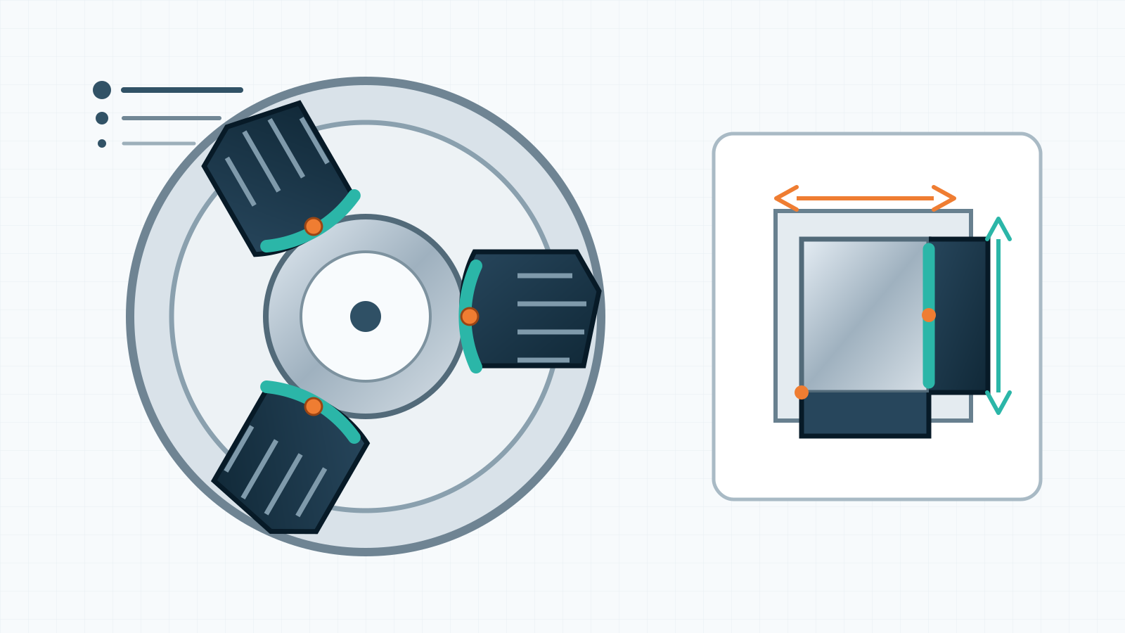
Technical diagram of three bored soft jaws supporting a CNC-turned workpiece
Conceptual illustration: soft jaws bored to the gripping diameter increase contact area. This is a technical diagram, not an actual VietTech production photograph; geometry and gripping force require part-specific validation.
03

Bore the jaws in a representative loaded state

During boring, the chuck mechanism should be loaded in the direction that represents external or internal gripping. A jaw-boring ring or loading fixture brings the mechanism closer to its production state. Boring unloaded jaws and then applying high production force can change contact because of elastic deformation and clearance. The bore diameter should match the intended gripping diameter while allowing reliable loading and seating. Do not apply one compensation value to every chuck; validate it on the actual machine, jaw material, force and trial part.

External gripping

The jaws move inward onto an outside diameter; the boring fixture should create the corresponding loaded condition.

Internal gripping

The jaws expand into a bore; loading direction and contact geometry must suit that mode rather than copying an OD setup.

04

Contact diameter and grip length determine stability

Uniform contact avoids edge loading, marking and slip. A jaw bore that is too small or large may contact only at an edge. Too little grip length reduces resistance to cutting torque; too much may block a machined face or trap chips. An axial stop can control length, but it must clear radii, chamfers and stock and remain chip-free. For thin parts, increasing support area is often safer than increasing pressure. Full-grip, six-point or dedicated fixtures may be better when three contacts still distort the component.

05

There is no universal chuck pressure

Grip must resist cutting force and rotational inertia without deforming the part, damaging its surface or overloading the jaws. Hydraulic pressure is not the same as force at the workpiece; cylinder area, chuck mechanism, jaw position, lubrication, speed and wear affect the relationship. For thin sleeves and rings, use a controlled trial, compare measurements while clamped and free, and confirm release-and-regrip repeatability. A part that measures correctly in the chuck but changes after release may have a workholding problem rather than a tool-offset problem.

SymptomPossible causeCheckAction
Runout changes after regrippingPoor seating, chips or incorrect contact diameterIndicator and repeated release/regripClean, verify stop, rebore if justified
Round in chuck, lobed after releaseExcess force or narrow contactMeasure clamped and freeReduce approved force, increase support or change fixture
Clamping marksLocal pressure, jaw burr or trapped chipVisual inspectionDeburr, clean and select suitable jaw contact
Jaw set loses concentricityWrong position, worn interfaces or collisionCheck jaw numbering and reference runoutRestore correct position and inspect chuck
06

Preserve jaw position and history

Mark the chuck, jaw number, gripping diameter, gripping direction and operation. A set moved to another position or chuck cannot be assumed to retain its previous concentricity. Serrations, guides and bolts must be clean and undamaged and assembled to equipment instructions. Recheck after a collision, chuck service, master-jaw replacement or major force change. Repeated reboring reduces jaw section and stiffness; retire the set before thread engagement, section or safe envelope becomes inadequate.

07

Plan roughing, datum creation and finish gripping together

A common route uses hard jaws for roughing and creating a face and reference diameter, then reverses the part into bored soft jaws for finishing. Related concentric features should be finished in one setup where practical. Select the stop, grip diameter and inspection surface from the drawing datum chain, not merely from the easiest place to hold. Approve the first piece after checking datum runout, axial seating and free-state size. During the lot, monitor chip contamination, heat, jaw wear and force.

08

Inspection should include regrip repeatability

Runout in one clamping cycle does not show how the setup behaves after release. If the part must be reloaded or assembled from the gripped datum, test several release-and-regrip cycles. Measure geometric requirements from the drawing datum and state whether a flexible part is inspected free or restrained. VietTech machines and inspects within the confirmed equipment, drawing and inspection plan; it does not promise one universal runout value for every chuck, diameter and material.

09

RFQ checklist

Provide matching 2D and 3D revisions, datums, allowable gripping zones, cosmetic restrictions, free-state tolerances, quantities and inspection needs. For repeat work, lot size and frequency help determine whether bored soft jaws, full-grip jaws or a dedicated fixture is appropriate.

  • Diameter and length available for gripping
  • Datum, runout, concentricity and inspection state
  • Cosmetic or no-mark surfaces
  • Material, hardness and treatment state
  • Prototype and repeat-lot quantities
  • Report and regrip-repeatability requirements
010

Technical sources and limits

This article references Kitagawa's 2026 technical catalogue for soft jaws and jaw-boring rings, and SCHUNK technical information on turned jaws, contact area, distortion reduction and surface protection. The chuck manufacturer's speed, stroke, jaw-force and safety instructions govern the setup. This guide does not replace workholding calculations, trial cuts or a part-specific risk assessment.

RELATED PAGES

CNC Machining Thin-Wall Parts: Reducing Vibration and Distortion ↗Circular Runout vs Total Runout: What Is the Difference on a Drawing? ↗CNC Burr Control: Through Holes, Intersecting Bores and Tool-Exit Edges ↗How to Request a Quote ↗

FAQ

Frequently asked questions

Do soft jaws guarantee zero runout?

No. They can improve contact and location, but the chuck, boring method, datum, force, chips and regripping all affect runout.

Can one soft-jaw set grip a nearby diameter?

Only after checking contact, grip length and safety. A small difference can create edge contact; reboring or another set is often required.

Does higher gripping pressure improve accuracy?

Not necessarily. Excess force can distort the part, mark the surface and change size after release.

Why use a jaw-boring ring?

It loads the chuck mechanism closer to production conditions while the jaw diameter is machined.

Should a thin part be measured clamped or free?

Follow the drawing and functional state. Free-state acceptance requires measurement after release; clamped data remains useful for diagnosing workholding distortion.

CNC MACHINING

Need a turning-workholding review?

Send the 2D/3D data, material, quantity, datums, allowable gripping area and runout requirements. VietTech will review the turning sequence, soft-jaw concept and inspection plan before quotation.REQUEST A QUOTE ↗