
CNC MACHINING

CNC Burr Control: Through Holes, Intersecting Bores and Tool-Exit Edges

How to anticipate, reduce and inspect burrs at through holes, intersecting bores, threads and tool-exit edges—and specify the requirement in an RFQ.

CNC MACHININGVIETTECH · TECHNICAL RESOURCES
01

A burr can be a functional risk, not merely a cosmetic defect

A burr is displaced or projecting material left at an edge after cutting. On a cover plate it may mainly affect handling, but at a dowel bore, seal, guide slot, thread, oil passage or clean cavity it can obstruct assembly, scratch a mating part, cut a seal, retain chips or create contamination. A blanket note such as “no burrs” therefore gives too little information for process planning and acceptance. The RFQ should identify functional edges, the required edge condition, areas where loose material is prohibited and the expected inspection method. This separates a safe-handling requirement from a controlled geometric edge.

02

Where do burrs usually form?

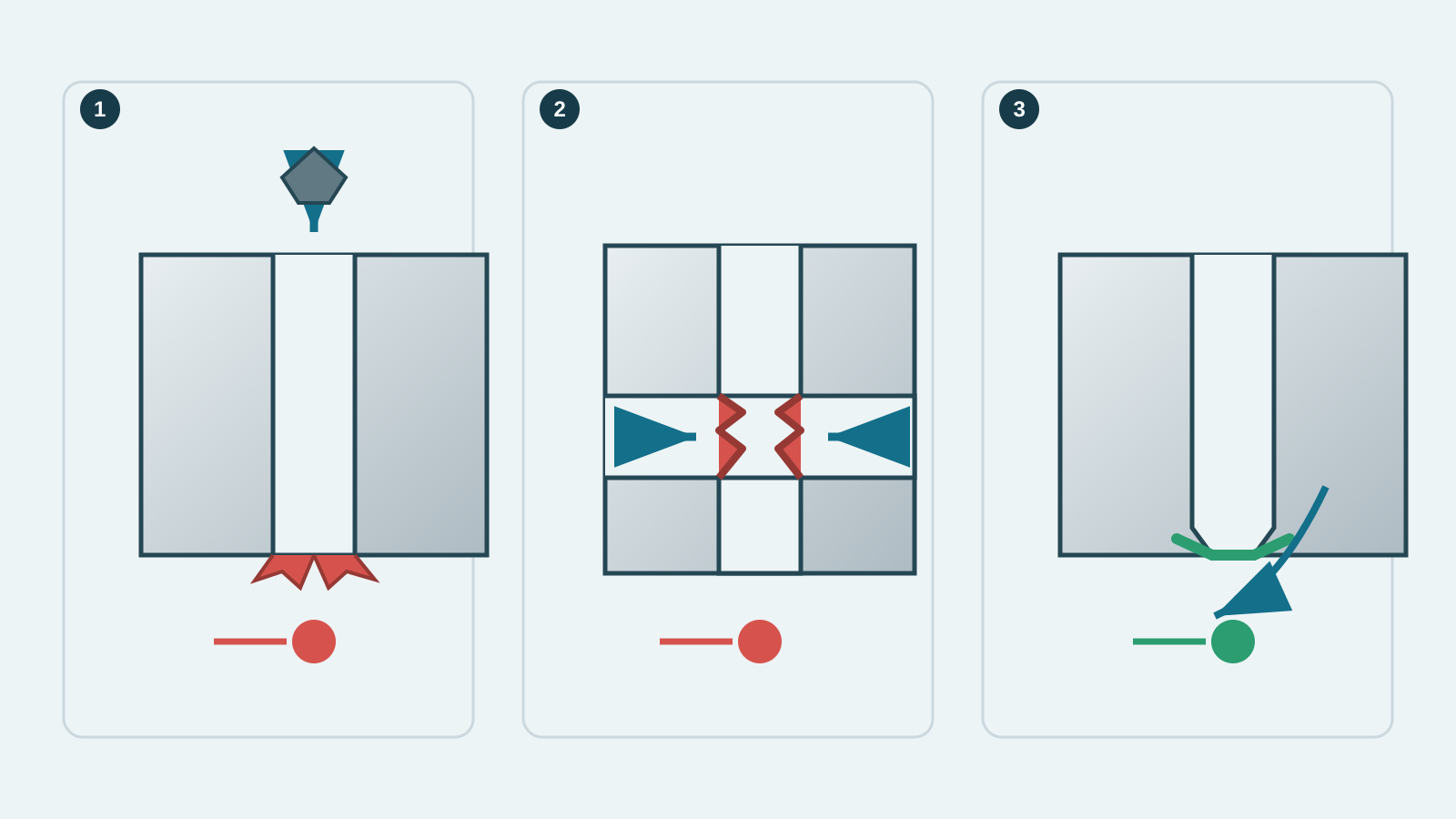
Burr location and shape depend on the cutting mechanism, tool condition, exit direction, fixturing rigidity and material ductility. At drill breakthrough, the last unsupported layer can deform before it is fully cut. Intersecting bores create internal edges that may be hard to see or reach. In profile milling, the exit side often concentrates the burr; changing the toolpath can move it to a more accessible edge, provided stability and surface quality remain acceptable. Threads, narrow grooves and deep bores can retain burrs or develop secondary burrs after edge breaking.

Technical diagram of burrs at a through-hole exit, intersecting bores and a finished edge
Conceptual illustration: through-hole exit burr, intersecting-bore burr and a controlled finished edge. This is a technical diagram, not an actual VietTech production photograph.
03

Map the risk before choosing a removal method

Classify edges by function instead of imposing one note on the entire part. One edge may be accessible but next to a datum; another may be deep inside an intersecting bore. The table is a DFM discussion aid, not a default acceptance standard.

LocationMain riskControl directionSuitable verification
Through-hole exitRaised lip, chipping, assembly interferenceExit support, sharp tool, controlled edge breakVisual/magnified inspection or drawing-defined gauge
Intersecting boresHidden burr, trapped chip, restricted flowOperation sequence, back-deburring or special toolBorescope or process validation based on risk
Thread start/endAssembly scratching, incomplete thread crestLead chamfer and thread cleaningGO/NO-GO gauge plus edge inspection
Precision fit edgeFunctional size changeMachine a separately dimensioned edgeMeasure chamfer/radius and fit size
Handling edgeSharpness and operator riskAppropriate sharp-edge removalAgreed visual/tactile criterion
04

Reduce burr formation in the CNC operation

The most stable approach is often to reduce burr creation before adding a cleaning step. Tool wear, runout, weak support, recutting chips and an unsupported exit layer all worsen the edge. Depending on geometry, the process engineer may consider drilling from both sides, adding backing support, moving the exit to an accessible area, or using a dedicated chamfering operation. An angled exit or a bore crossing another bore changes the engagement continuously, so the strategy must be tested with the actual material and setup. There is no universal feed, chamfer or edge radius for every part.

Through holes and angled exits

Support the exit where practical, monitor drill condition and avoid pushing the final material layer out. Angled exits and cross-holes require separate review of tool geometry and approach.

Profile milling and thin edges

Milling direction, cut sequence and tool-exit location influence which face carries the burr. Do not move the exit merely to relocate a burr if it reduces rigidity or creates chatter.

05

Select deburring by geometry

Options include on-machine chamfering, back-deburring tools, manual scrapers or stones, brushing, mass finishing and specialized processes. Each has limits. Manual work is flexible but depends on access and consistent work instructions. Mass finishing can blend many edges yet may affect finish, corner definition or small dimensions and does not guarantee a clean deep bore intersection. A cross-hole tool needs the main- and cross-bore diameters, depth, intersection angle, eccentricity and material. Chemical, thermal or electrochemical routes should only be considered when the requirement, material and qualified supply chain have been confirmed; they are not default VietTech operations.

06

How should the edge requirement appear on a drawing?

If an edge needs defined geometry, specify the chamfer or radius with an appropriate tolerance rather than relying on “break edge.” For edges of undefined shape, ISO 13715:2017 provides a method for indicating the permitted edge condition and deviation; it does not replace normal dimensioning for a defined edge such as 1 × 45°. Separate loose-burr restrictions, safe-handling edges and assembly-critical edges. Applying one generic value to small bores, threads, seals and outer edges can create conflict. Ambiguous symbols or notes require an RFI before quotation or manufacture.

07

Inspecting burrs and finished edges

Burr inspection is not one universal measurement. Suitable lighting or magnification can reveal projecting material and secondary burrs; a borescope may help at internal intersections, subject to access. A thread gauge verifies thread function but does not prove every burr has been removed. A dimensioned chamfer or radius needs a matching geometric method. For high-risk edges, define sampling, observation area, acceptance limit and any process validation. Chip removal and cleanliness are separate requirements: a deburred part is not automatically proven clean to a specified cleanliness level.

08

RFQ checklist for burr-sensitive parts

Provide a controlled 2D drawing and matching 3D model; identify cross-holes, seal edges, dowel fits, fluid paths and no-scratch surfaces. State whether the edge is dimensioned or only needs sharp-edge removal, how loose burrs are treated, any cleaning requirement and a mandatory inspection method. Include material, heat/surface condition, prototype and production quantities, and report needs. VietTech performs CNC machining, edge treatment and inspection within the scope confirmed for each drawing; specialized deburring or treatment is evaluated separately and may be coordinated with qualified partners.

  • Mark functional and inaccessible edges
  • Dimension chamfers/radii when geometry matters
  • Separate burr, cleanliness and appearance requirements
  • Agree on inspection method and sampling
09

Technical references and limits

This article uses ISO 13715:2017 for undefined-edge indication, NIST research on burr formation and removal, and application guidance from HEULE and Sandvik Coromant for intersecting or angled-exit holes. These sources explain principles only. Final edge dimensions, tools, cutting data and acceptance criteria must follow the drawing, contract standard and validation on the actual part.

RELATED PAGES

Drilling, Boring or Reaming: Which Process for Precision Holes? ↗Ra 3.2, Ra 1.6 and Ra 0.8: Choosing Surface Roughness for CNC Parts ↗How to Specify Materials and Surface Finishes in an RFQ ↗

FAQ

Frequently asked questions

Is “burr-free” the same as a C0.2 chamfer?

No. Burr-free describes the absence of unacceptable projecting material; C0.2 defines edge geometry. They are specified and verified differently.

Will mass finishing always remove a cross-hole burr?

No. Access, media, geometry, material and time all matter, and the process can also affect edge definition, roughness or dimensions.

Why can a burr return after edge breaking?

Tool wear, a later operation, edge deformation or cleaning can create a secondary burr. Inspect the final delivery condition.

How is a hidden bore intersection inspected?

A borescope, special gauge or validated process may be used depending on size and risk. Define the method in the inspection plan.

Can VietTech guarantee every part is absolutely burr-free?

The criterion must be measurable and accessible. VietTech confirms treatment scope, inspection areas and acceptance limits from the drawing/RFQ before committing.

CNC MACHINING

Need to control burrs on functional bores or edges?

Send the 2D/3D data, material, quantity, inaccessible-edge map and acceptance criteria. VietTech will review the machining, edge-treatment and inspection route before quotation.REQUEST A QUOTE ↗